Electrical connections, Wiring diagram, Warning – American Water Heater Power Flex 40-42K BTU User Manual
Page 13
13
ELECTRICAL CONNECTIONS
Before plugging in the water heater, always make sure:
•
The voltage and frequency correspond to that specified
on the water heater wiring diagram.
•
The electrical outlet has the proper overload fuse or
breaker protection.
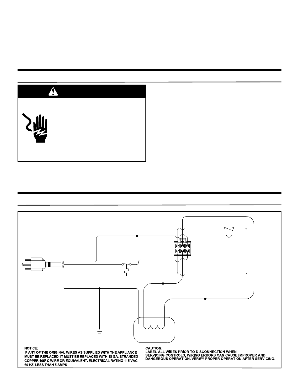
WIRING DIAGRAM
The Temperature and Pressure Relief Valve:
• Must not be in contact with any electrical part.
• Must be connected to an adequate discharge line.
• Must not be rated higher than the working pressure
shown on the data plate of the water heater.
The Discharge Line:
• Must not be smaller than the pipe size of the relief
valve or have any reducing coupling installed in the
discharge
line.
• Must not be capped, blocked, plugged or contain any
valve between the relief valve and the end of the
discharge
line.
• Must terminate a maximum of six inches above a
fl oor drain or external to the building.
• Must be capable of withstanding 250°F (121°C)
without
distortion.
• Must be installed to allow complete drainage of both
the valve and discharge line.
IMPORTANT: Do not use an extension cord to connect the
water heater to an electrical outlet.
•
The water heater and the outlet are properly grounded.
•
Installed in accordance with prevailing provisions of
local codes, or in the absence of such, National Electric
Code, ANSI/NFPA 70.
NOTE: Always reference the wiring diagram for the correct
electrical connections.
After making all electrical connections, completely fill the
tank with water and check all connections for leaks. Open
the nearest hot water faucet and let it run for 3 minutes to
purge the water lines of air and sediment and to ensure
complete filling of the tank. The electrical power may then
be turned on. Verify proper operation after servicing.
WARNING
Electric Shock Hazard
Disconnect power before
servicing.
Replace all parts and panels
before operating.
Failure to do so can result in
death or electrical shock.
WHITE
BLACK
GREEN
GREEN
WHITE
BLACK
MOTOR
120V 60Hz.
120V 60Hz.
TEMP.
SWITCH
BLUE
WHITE
WHITE/BLACK TRACER
YELLOW/BLACK TRACER
YELLOW
PRESSURE
SWITCH
YELLOW
GREEN
BLOWER GROUND
GAS VALVE CONNECTOR