Seiwa SW AP03 User Manual
Page 37
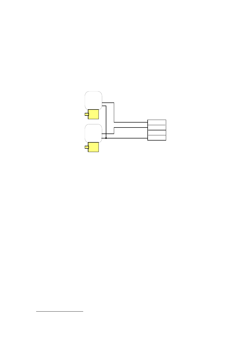
3.6.2. SOLENOID CONTROLLED HYDRAULICS
The motor-drive output of the Junction Box is suitable for direct connection to flow-
control solenoids, provided that their operating voltage is the same as the supply
voltage to the SW AP03 system and the solenoid current does no exceed 10A. The
connections to the Junction Box are shown in Fig 3.12.
IMPORTANT: Before connecting the solenoids, make sure that their wiring does not
have connections to ground or any other part of the vessel's wiring.
RIGHT
FLOW
LEFT
FLOW
MOTOR +
MOTOR -
CLUTCH -
CLUTCH +
Figure 3.12 Connection to flow-control solenoids.
3.6.3 HYDRAULIC SYSTEM WITH REVERSING HYDRAULIC PUMP
Connecting autopilot pumps to hydraulic systems from different manufacturers is
not difficult and the following guidelines will be adequate for most installations. If there
is a doubt about the correct way to proceed, consult the manufacturer of the steering
gear.
The following installation schematics show an OPTIONAL LOCK VALVE. Though this
is not essential for the normal operation of the system, it is an additional safeguard in
the unlikely event of the failure of the pump. This valve isolates the system into two
completely independent sources of steering power and, if required, can be supplied by
your Distributor.
To connect the motor, simply use the pins “motor +” e “motor -”.
35