Seiwa SW AP03 User Manual
Page 32
But in steel hulls, some trial and error may be needed to find the best position.
Generally, the compass will not perform well if totally enclosed in a steel structure.
Further notes on mounting in a steel vessel are given below.
Mount the S81.02 compass on a vertical surface with its mounting flange towards the
bow and the cable entry facing down. (The compass will not operate correctly if
mounted upside down.) Corrections for small errors in orientation can be made via the
heading adjust menu option in the autopilot. Lay the cable back to the Junction Box,
following the same method and precautions as for the controller cable and terminate it
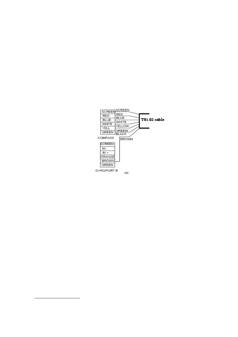
in the Compass socket as shown in Fig 3.4.
The S81.02 cable has 6 conductors, plus a screen. Five of these are connected to the
Compass socket, as in Fig 3.4(a). The sixth (brown) is connected to the brown pin on
the Gyro/Port B socket.
Figure 3.4. Socket connections for the S81.02 compass
Steel Vessels
Steel hulls distort the natural pattern of the earth's magnetic field. In many cases these
deviations can be adjusted out through the calibration procedures. In others, a strong
vertical field component may exist which will prevent the compass giving good
performance. It is recommended that the compass be mounted temporarily so that the
best site can be found by experimenting. The following notes should help find the best
mounting:
1.
In the first instance, try siting the compass unit below decks but centrally
within the vessel. Keep well clear of vertical steel bulkheads and position
the compass at least 45 cm (18 in) above a steel floor.
30