Seiwa SW AP03 User Manual
Page 30
Before commencing the wiring, isolate the vessel’s power bus from the power supply.
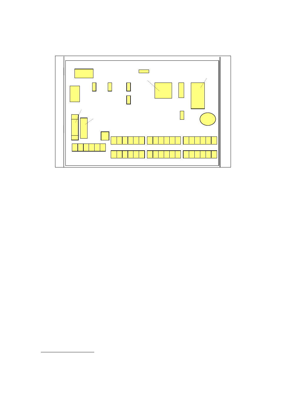
Note that all connections to the Junction Box, except for motor and power, are made to
removable plugs. Figs 3.1 show the location of the sockets and principal components
for the TM81.01.
POWER
20A FUSE
MOTOR/CL
RELAY
RELAY
MICROPROCESSOR
PROGRAM STORE
COMPASS
REMOTE
CONTROLLER
RUDDER MTR ALM
NMEA
GYRO
0.8A
FUSE
PORT B
Figure 3.1 Layout of S81.01 Junction Box components
and connectors.
The quality of the power supply to the Junction Box is important for reliable operation.
Large voltage spikes caused by switching other electrical gear on the vessel, or the
supply voltage moving outside the specified limits can cause the system to reset.
These problems are reduced by using heavy wiring and connecting the system to a
point as close as practical to the main batteries.
Lay a 30 amp twin-core cable to the vessel's power bus, slipping a grommet over the
cable where it enters the Junction Box and connecting the cable to the terminal block.
It is also recommended that a 20 or 30 amp switch is installed between the Junction
Box and the power bus so that the autopilot can be isolated during unattended periods.
28