Warning, Warranty – Norgren 3222-1 User Manual
Page 2
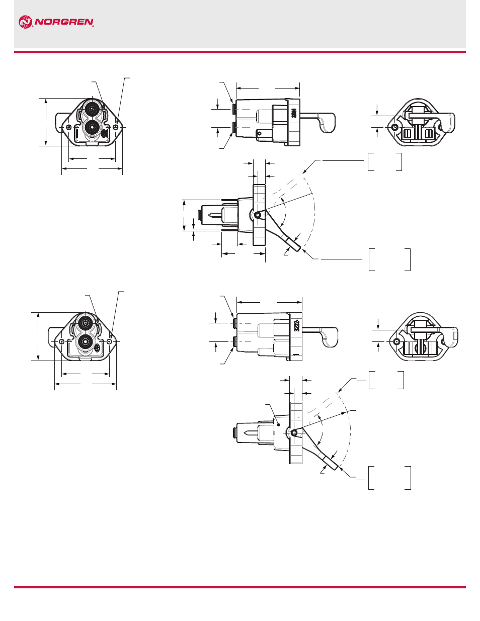
3220-1
3222-1
Our policy is one of continued research and development. We therefore reserve the right to amend,
without notice, the specifications given in this document.
© Norgren GT Development Corporaton, 2014
Standard Flipper Valve 3220-1, 3222-1
1.51
10-24 UNC
THREADS
TYP 2 PL
EXHAUST
REGION
2 PL
1.50
1.95
0.58
INLET WITH
PTC FITTING
OUTLET WITH
PTC FITTING
2-1/16
3/8
0.40
0.25
AIR
ON
INLET
CONNECTED
TO OUTLET
R1.70± 0.02
75° ±3
0.18
INLET BLOCKED
OUTLET
CONNECTED
TO EXHAUST
ELECTRICAL
CLOSED
AIR
OFF
ELECTRICAL
OPEN
1.00
0.032
17/32
1-13/32
1.51
10-24 UNC
THREADS
TYP 2 PL
EXHAUST
REGION
2 PL
1.50
1.95
0.58
REF
INLET WITH
PTC FITTING
OUTLET WITH
PTC FITTING
2-1/16
3/8
AIR
ON
INLET
CONNECTED
TO OUTLET
R1.70± 0.02
0.18
AIR
OFF
INLET BLOCKED
OUTLET
CONNECTED
TO EXHAUST
75° ±3
YELLOW DOT
APPROX. 1/8 DIA.
0.40
0.25
BOTTOM VIEW OF VALVE
AS TYPICALLY INSTALLED
Warning
Improper selection, misuse, age or malfunction of components used in
commercial vehicle systems can cause failure in various modes. The system
designer is warned to consider the failure modes of all component parts
used in commercial vehicle systems and to provide adequate safeguards to
prevent personal injury or damage to equipment or property in the event of
such failure modes. System designers and end users are cautioned to consult
instruction sheets and specifications available from the factory. The system
designer/end user is responsible for verifying that all requirements for the
application are met.
Warranty
The products described herein are warranted subject to seller’s Standard
Terms and Condition of Sale, available at seller’s website.
Dimensions (Inches)
REV: 8/14
02