Norgren P72F Series Installation Instructions User Manual
P72f
OPERATION
Normally closed, 3-way valves block inlet air and
exhaust downstream air when the solenoid is de-energized.
Air flow from the inlet port to the outlet port occurs when
the solenoid is energized.
The soft start function reduces the rate of downstream
pressure buildup at system start up. Cylinders and other air
operated devices are eased into normal starting positions,
reducing the possibility of equipment damage and hazards
to the user.
Solenoid operated valves can be actuated and
deactuated manually when the solenoid is de-energized by
depressing the manual override. Depress override to
actuate the valve. Release override to deactivate valve.
Turn on the system air supply prior to applying pilot
signal to operator. Failure to do so may cause valve to
continuously exhaust.
INSTALLATION
1. Shut off air pressure. Make sure pressure upstream and
downstream of the valve has been reduced to zero.
Install valve in air line -
!
with air flow in direction of arrow on body,
!
upstream of the air circuit requiring protection,
!
with sufficient clearance to remove parts for service.
2. Connect piping to proper ports using pipe thread sealant
on male threads only. Do not allow sealant to enter
interior of valve.
3. Install a muffler in the exhaust port. Order Norgren
muffler MB002B for valves with a Rc1/4 exhaust port or
MB002A for valves with a 1/4 PTF exhaust port. Exhaust
can also be piped away. Install pipe work at a downward
angle from the valve to provide drainage.
4. Any electrical connections must be made by a
competent, licensed electrician.
5. Install a compressed air filter and lubricator immediately
upstream of the valve. Install lubricator between the
filter and valve. Lubricator should be capable of
atomizing oil at low as well as high air flow. See
Norgren Publication N/AL.8.900.935 for recommended
lubricants.
Adjustment
1. The time required to reach full pressure is dependent on
the downstream system volume. Units shipped from
factory are set to give maximum delay.
2. To adjust time delay:
a. Turn on system air supply prior to
applying pilot signal to operator.
Failure to do so may cause valve
to continuously exhaust.
b. Actuate the solenoid (press and
hold solenoid override if your
solenoid is so equipped), or apply
the air pilot signal on air pilot
operators.
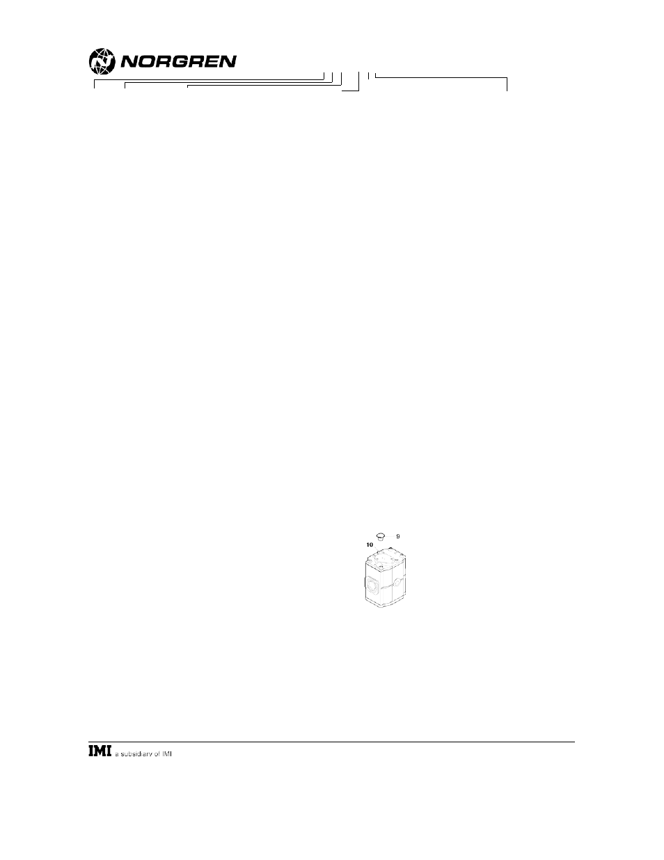
c. Remove tamper resistant plug (9).
d. Use a 3 mm allen key to turn
adjusting screw (10) clockwise to
increase and counterclockwise to decrease time delay.
c. Reinstall tamper resistant plug (9).
TECHNICAL DATA
Valve type: 3-way, normally closed, soft start
Fluid: Filtered and lubricated compressed air
Main valve maximum inlet pressure: 17 bar (250 psig) but
must not exceed the solenoid rating when solenoid
operator is used
Minimum inlet pressure: 3 bar (44 psig)
Operating temperature*: -20° to +65°C (0 to150°F) but
must not exceed the solenoid rating when solenoid
operator is used
* Air supply must be dry enough to avoid ice formation at
temperatures below 35°F (2°C).
Air operator pilot supply inlet pressure range: Equal to or
greater than the main valve inlet pressure, but not less
than 3 bar (44 psig) and not greater than 17 bar (250
psig).
Maximum flow with 6,3 bar (90 psig) inlet pressure and a
pressure drop of 0,5 bar (7 psig): 21 dm
3
/s (45 scfm)
Average flow factor (Cv) –
IN to OUT Port: 1,59
OUT to EXHAUST Port: 1,72
Snap pressure: Full flow when downstream pressure
reaches 50 to 80% of inlet pressure.
Adjustable charge time for 2 litre (2 U.S. quart)
downstream volume at 6.3 bar (90 psig) inlet pressure:
0,8 seconds minimum to 99 seconds maximum
Pilot port on air operated regulators:
M5 with ISO main ports
10-32 with PTF main ports
Exhaust port:
Rc1/4 with ISO main ports
1/4 PTF with PTF main ports
Materials:
Body: Zinc
Internal components: Brass/steel
Filter discs: Sintered plastic
Elastomers: Nitrile
P72F Soft Start Valve
Installation & Maintenance
Instructions
IM-160.610
(10/01)
Supersedes 9/97
© Norgren 2001
P72F - """ - """
Solenoid Operator
Watts
Voltage
A.......110/120 50/60 Hz .......4/2,5 VA
B.......220/240 50/60 Hz .......4/2,5 VA
D.......6 Vdc.............................2W
E .......12 Vdc...........................2W
F .......24 Vdc...........................2W
Z .......No coil
N.......No Solenoid
Connector
A....Cable grip
N....No connector
Operator
A....Air pilot
C....22 mm solenoid
L....CNOMO solenoid
N....None
Solenoid Override
P....Non-locking,
shrouded
push button
N....None
Port
2....1/4"
3....3/8"
Thread Form
A....PTF
B....ISO Rc taper
G....ISO G parallel
MAINTENANCE
The P72F valve is not field repairable, and must be returned
to the factory for repair in case of malfunction. Do not
attempt to disassemble or repair the P72F valve in the field.
WARNING
These products are intended for use in industrial
compressed air systems only. Do not use these products
where pressures and temperatures can exceed those listed
under Technical Data.
The user of these products is cautioned to conform to
all applicable electrical, mechanical, and other codes in the
installation and operation of these products.
Through misuse, wear or malfunction, these products
can fail in modes which can simultaneously pressurize all
ports to the highest applied pressure level. They can also
fail to shift as expected upon the application or removal of
operator signals. The system designer is warned to
consider the failure modes of all component parts used in
the system, and to provide adequate safeguards to prevent
personal injury or damage to equipment in the event of
such failures. System designers must provide a warning to
end users in the system instructional manual if protection
against a failure mode cannot be adequately provided.
The P72F valve must be returned to the factory for
repair in case of malfunction.
Do not use these valves to control a power press clutch
or brake.
Before using these products with fluids other than air,
for nonindustrial applications, or for life-support systems
consult Norgren.