Ale-8-5, Typical performance characteristics service kits, Technical data – Norgren 20AL Series User Manual
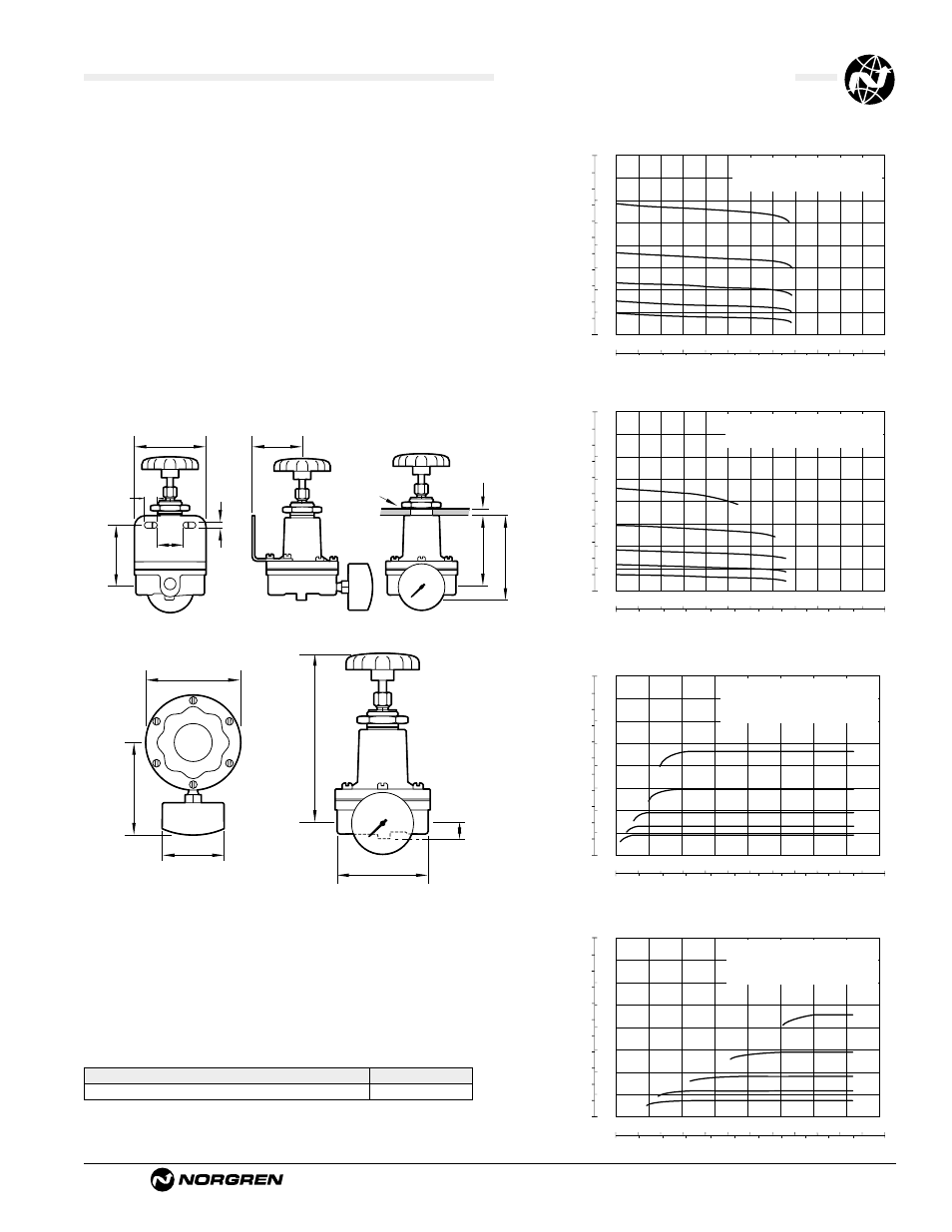
Page 2: Mounting dimensions
ALE-8-5
All Dimensions in Inches (mm)
Littleton, CO USA
Phone 303-794-2611
www.norgren.com
11-400 and 20AL Pilot Regulators
Typical Performance Characteristics
Service Kits
Type
Part number
11 400-20AL-X
11 400-100/20AL
Service kit includes: diaphragm assemblies, valve assembly, valve spring o-
rings and valve seats for pilots.
Technical Data
Fluid: Compressed air filtered to 5µm
Maximum inlet pressure: 360 psig (25 bar)
Operating temperature: 0° to 175°F (-20° to 80°C) *
* Air supply must be dry enough to avoid ice formation at temperatures below 35°F (2°C).
Typical flow with 100 psig (7 bar) inlet pressure, 23 psig (1.6 bar) set pressure and
1.5 psig (0.1 bar) droop from from set: 4.2 scfm (2 dm3/s)
Gauge ports: 1/8" PTF
Materials:
Body, bonnet: Zinc
Elastomers: Nitrile
0 2 4 6 8 10 scfm
0 1.0 2.0 3.0 4.0 5.0 dm
3
/s
Air Flow
bar,g
psig
Secondary Pressure
24
16
8
0
1.6
1.2
0.8
0.4
0
FLOW CHARACTERISTICS
PORT SIZE: 1/4 "
INLET PRESSURE: 100 psig (7 bar)
RANGE: 1 to 30 psig (0.06 to 2 bar)
0
20 40 60 80 100 120 140 psig
0 2 4 6 8 10 bar
bar,g
psig
Second
ary Pressure
30
20
10
0
2
1.5
1
0.5
0
Primary Pressure
REGULATION CHARACTERISTICS
1.3 scfm
0.8 scfm
0.6 scfm
0.4 scfm
1.8 scfm
PORT SIZE: 1/4 "
INLET PRESSURE: 150 psig (10 bar)
RANGE: 1 to 30 psig (0.06 to 2 bar)
Curves are 50% of recommended flow
0 2 4 6 8 10 scfm
0 1.0 2.0 3.0 4.0 5.0 dm
3
/s
Flow
bar,g
psig
Secondary Pressure
100
80
40
0
8
6
4
2
0
FLOW CHARACTERISTICS
PORT SIZE: 1/4 "
INLET PRESSURE: 100 psig (7 bar)
RANGE: 2 to 100 psig (0.16 to 7 bar)
0 20
40 60 80 100 120 140 psig
0 2 4 6 8 10 bar
bar,g
psig
Second
ary Pressure
100
80
40
0
8
6
4
2
0
Primary Pressure
REGULATION CHARACTERISTICS
6.0 scfm
3.9 scfm
2.7 scfm
1.8 scfm
1.3 scfm
PORT SIZE: 1/4 "
INLET PRESSURE: 150 psig (10 bar)
RANGE: 2 to 100 psig (0.16 to 7 bar)
Curves are 50% of recommended flow
3.15 (80)
3.35 (85)
1.97 (50)
5.70 - 6.50 (145 - 165)
.55 (14)
3.15 (80)
g
2.17 (55)
1.26 (32)
2.76 (70)
0.28 (7)
.63 (16)
(typ 2)
3.35 (85)
.40 (10) max .20 (5) min
3.15 (80)
3.74 (95)
panel mount
hole 1.062 (27)
Mounting Dimensions
(Shown with optional gauge and mounting bracket)