Norgren B38SS Series Installation Instructions User Manual
B38 (1/4" ported units), Installation & maintenance instructions, Stainless steel instrument regulator b38 - 2
B38 (1/4" Ported Units)
Installation & Maintenance
Instructions
ADJUSTMENT
1. Before applying inlet pressure to filter/regulator, turn
adjustment (1) counterclockwise to remove all force on
regulating spring (6).
2. Apply inlet pressure, then turn adjustment (1) clockwise to
increase and counterclockwise to decrease outlet pressure
setting.
3. Always approach the desired pressure from a lower
pressure. When reducing from a higher to a lower setting,
first reduce to some pressure less than that desired, then
bring up to the desired pressure.
NOTE
With non-relieving filter/regulators, make pressure
reductions with some air flow in the system. If made
under no flow (dead-end) conditions, the
filter/regulator will trap the over-pressure in the
downstream line.
4. Tighten locknut (2) to lock pressure setting.
SERVICING
1. Open manual drain to expel accumulated liquids. Keep
liquids below element retainer (28).
2. Replace filter element (30) when dirty (check inner surface
of element), or when pressure drop across element
exceeds 0,7 bar (10 psig).
DISASSEMBLY
1. Filter/regulator can be disassembled without removal from
air line.
2. Shut off inlet pressure. Reduce pressure in inlet and outlet
lines to zero.
3. Turn adjustment screw (1) fully counterclockwise.
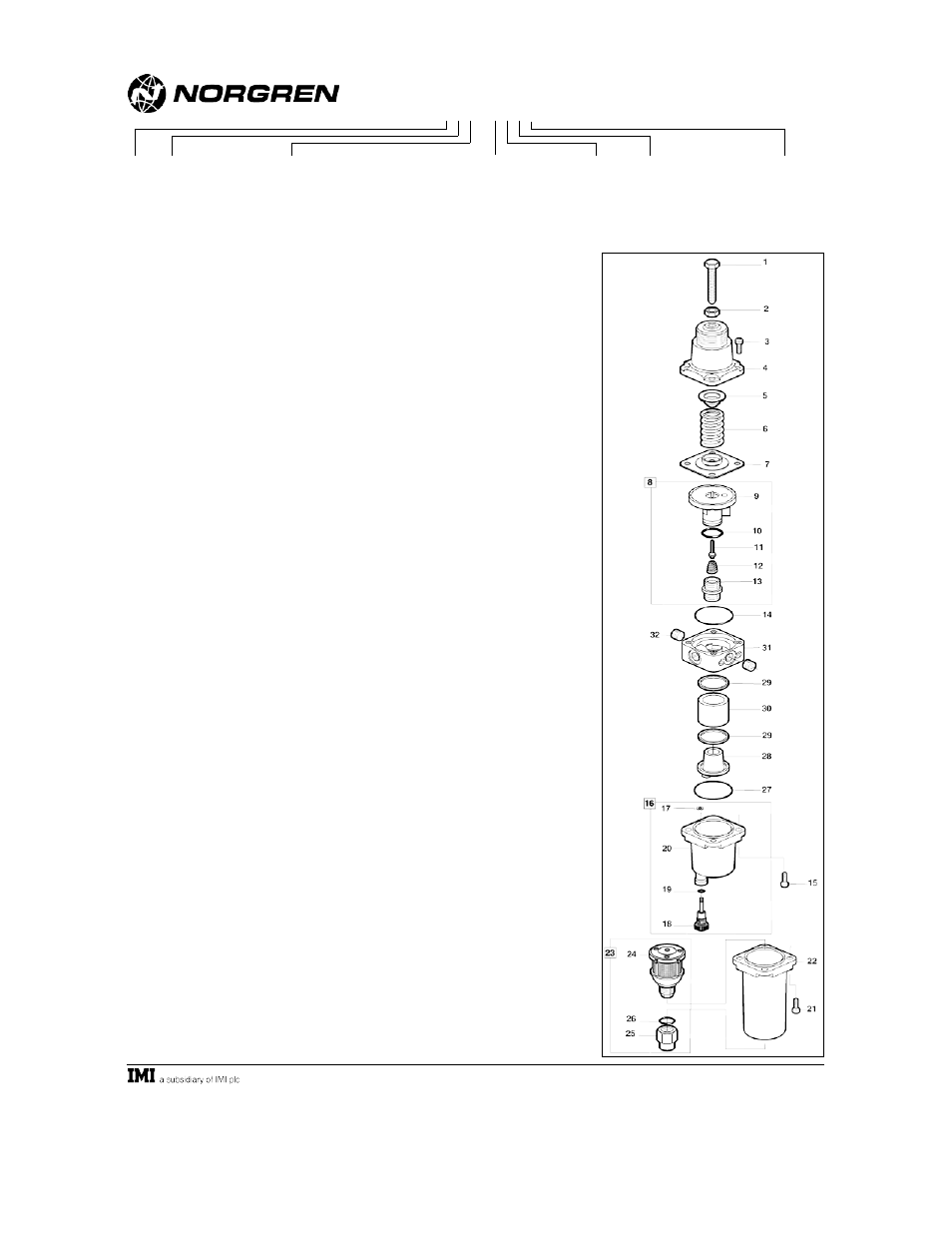
4. Disassemble in general accordance with the item numbers
on exploded view. Do not remove the drains unless
replacement is necessary. Remove and replace drains only
if they malfunction.
CLEANING
1. Clean parts with warm water and soap.
2. Rinse and dry parts. Blow out internal passages in body
(31) with clean, dry compressed air.
3. Inspect parts. Replace those found to be damaged.
ASSEMBLY
1. Lubricate threads of adjusting screw (1), recess of upper
sprint rest (5), and o-rings with a light coat of good quality
o-ring grease.
2. Assemble the unit as shown on the exploded view.
Assemble bonnet (4) to body (31) so that relief hole is
above outlet port.
3. Torque Table
Item
Nm
(Inch-Pounds)
3, 15, 21 (screws)
3,3 to 7,3 (30 to 66)
28 (element retainer)
1,3 to 1,7 (12 to 15)
CAUTION
Water vapor will pass through these units and could
condense into liquid form downstream as air temperature
drops. Install an air dryer if water condensation could have a
detrimental effect on the application.
WARNING
These products are intended for use in industrial
compressed air systems only. Do not use these products
where pressures and temperatures can exceed those listed
under Technical Data.
If outlet pressure in excess of the regulator pressure
setting could cause downstream equipment to rupture or
malfunction, install a pressure relief device downstream of
the regulator. The relief pressure and flow capacity of the
relief device must satisfy system requirements.
The accuracy of the indication of pressure gauges can
change, both during shipment (despite care in packaging)
and during the service life. If a pressure gauge is to be used
with these products and if inaccurate indications may be
hazardous to personnel or property, the gauge should be
calibrated before initial installation and at regular intervals
during use.
Before using these products with fluids other than air, for
non industrial applications, or for life-support systems
consult Norgren.
TECHNICAL DATA
Fluid: Compressed air
Maximum pressure:
Manual drain: 31 bar (450 psig)
Automatic drain: 17 bar (250 psig)
Operating temperature: -40° to +80°C (-40° to +175°F)*
* Air supply must be dry enough to avoid ice formation
at temperatures below +2°C (+35°F).
Particle removal: 5 µm or 25 µm filter element
Air quality: Within ISO 8573-1, Class 3 and Class 5
(particulates)
Typical flow with 12 bar (175 psig) inlet pressure, 8 bar
(115 psig) set pressure and a droop of 1,0 bar (15
psig) from set: 7 dm
3
/s (15 scfm)
Maximum bleed flow at 2 bar (30 psig) outlet pressure
(relieving models only): 1,5 cm
3
/s (0.003 scfm)
Automatic drain connection: 1/4-18" NPTF
Automatic drain operating conditions (float operated):
Bowl pressure required to close drain: Greater than
0,3 bar (5 psig)
Bowl pressure required to open drain: Less than
0,2 bar (3 psig)
Minimum air flow required to close drain:1 dm
3
/s
(2 scfm)
Manual operation: Depress pin inside drain outlet
Nominal bowl size:
Short bowl with manual drain: 25 ml (1 fluid oz)
Long bowl with automatic drain: 25 ml (1 fluid oz)
Gauge ports: 1/4", thread form same as main ports
Relief port: 1/8", thread form same as main ports
Materials:
Body, bonnet, bowl, adjusting screw: Stainless steel
Elements:
5 µm: Stainless steel
25 µm: High density polyethylene
Elastomers: Nitrile
SERVICE KITS
Regulator - items 3, 7, 11, 12, 15, 21, 27
Relieving, 2 bar spring ..........................................R38-100R
Relieving, 4 and 7 bar spring ................................R38-101R
Relieving, 10 bar spring ........................................R38-102R
Non-relieving, 2 bar spring .................................R38-100NR
Non-relieving, 4 and 7 bar spring .......................R38-101NR
Non-relieving, 10 bar spring ...............................R38-102NR
Filter - items 3, 17, 18, 19, 27, 30
Filter, 5 µm element...........................................B38-100S(5)
Filter, 25 µm element.......................................B38-100S(25)
PANEL MOUNTING DIMENSIONS
Panel mounting hole diameter: 42 mm (1.65")
Maximum panel thickness: 6 mm (0.24")
INSTALLATION
1. Shut off air pressure. Install filter/regulator in air line -
!
vertically (bowl down),
!
with air flow in direction of arrow on body. In some cases
IN
is stamped next to the inlet port.
!
upstream of lubricators and cycling valves,
!
as close as possible to the device being serviced.
2. Connect piping to proper ports using pipe thread sealant on
male threads only. Do not allow sealant to enter interior.
3. Flexible tube with 3mm (0.125") minimum I.D. can be
connected to the automatic drain. Avoid restrictions in the
tube.
4. Install a pressure gauge or plug the gage ports. Gage ports
can also be used as additional outlets for regulated air.
© Norgren 2002
IM-510.315.01
(3/02)
Supersedes (1/99)
* Outlet pressure can be adjusted to pressures in excess of, and less than, those specified. Do not use these units to control pressures outside of the specified ranges.
Stainless Steel
Instrument Regulator
B38 - 2"" - """"
Material
4....Stainless steel with Nitrile
elastomers
5....Stainless steel with Viton
elastomers
Port
2....1/4"
Spring (Outlet Pressure Range) *
C....0,1 to 2 bar (1 to 30 psig)
F ....0,1 to 4 bar (1 to 60 psig)
K....0,3 to 7 bar (5 to 100 psig)
M...0,3 to 10 bar (5 to 150 psig)
Thread Form
A....PTF
B....ISO Rc
D....ISO G
Bowl/Drain
A....Long bowl/auto drain
B....Short bowl/manual drain
Element
1 .......5 µm
2 .......25 µm
Diaphragm
0....Relieving
1....Non-relieving
2....Relieving with wall bracket and panel nut
3....Non-relieving with wall bracket and panel nut
4....Relieving with panel nut
5....Non-relieving with panel nut