Switching capacity, Recommended circuit, Switching function – Norgren 18D Pressure Switch Datasheets User Manual
Page 3
Our policy is one of continued research and development. We therefore reserve the right to amend,
without notice, the specifications given in this document. © 2013 Norgren GmbH
12/13
1998-5249c
N/en 5.11.001.03
18D
Switching capacity
Commutator with gold plated contacts
Current
type
Load type
*2)
U min
[V]
Max. permanent current Imax [A] at U *1)
(UL & CSA)
M 12x1 DIN EN 175301-803, form A
30 V 30 V 48 V 125 V 250 V
Contact life
AC
ohmic, inductive
6
0,1
0,1
0,1
0,1
0,1
≥ 2 x 10
5
switching cycles
DC
ohmic, inductive
6
0,1
—
—
—
—
Reference number: 20/min, Reference temperature: +20°C.
I min = 1 mA at 24 V DC or 5 mA at 6 V DC
*1) Higher currents (5 A max) will cause a reduction of the durability of the micro-switch contacts. Futhermore additional measuements has to be taken to
fulfil the EMV regulation 2004/108/EG by the manufacturer
*2) Spark quenching/overload protection will be necessary using inductive loads.
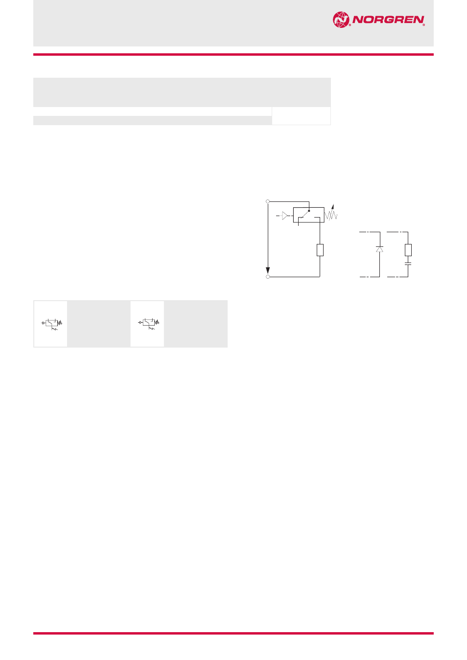
Recommended circuit
Spark quenching and EMV intrinsically safe
1. Quick diode (D) with tv
≤
200 ns, parallel to inductive load.
2. RC link in parallel to load in parallel to switching contact.
Dimensioning principles:
R
L
in W
≈
0,2 x RLoad in W
C in [µF]
≈
ILoad in [A]
+
-
p
D
1)
2)
R
C
R
L
U
DC (AC)
d.c (a.c.)
~
~
2
3
1
p
2
4
1
p
Switching function
Plug DIN EN 175301-803, form A
Microswitch SPDT
Terminals 1 - 3: Contacts close
on rising pressure.
Terminals 1 - 2: Contacts open
on rising pressure.
Switching function
IEC 947-5-2, M12 x 1:
Microswitch SPDT
Terminals 1 - 4: Contacts close
on rising pressure.
Terminals 1 - 2: Contacts open
on rising pressure.
R
L
= Load resistance