Norgren Air Solenoid Accessory Pack User Manual
Page 2
6/11
N/US
5.4.405.02
Our policy is one of continued research and development. We therefore reserve the right
to amend, without notice, the specifications given in this document.
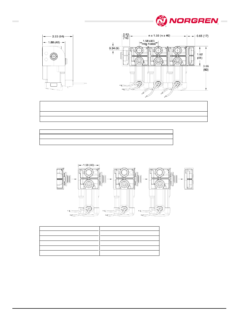
Air Solenoid Accessory Pack
Dimensions in Inch (mm)
C
Cooddee
P
Paarrtt N
Nuum
mbbeerr
F
Fuunnccttiioonn
E
Elleeccttrriiccaall
P
Poorrtt
V
Voollttaaggee
C
Coonnnneeccttiioonn
S
Siizzee
A
A
7201-70
3/2 NC
19" flying leads
(1/4" PIF)
12Vdc
A
A
7239-58
3/2 NC
19" flying leads
(1/4" PIF)
24Vdc
P
Paarrtt N
Nuum
mbbeerr D
Deessccrriippttiioonn
48C34901
1/4" Red
48C34902
1/4" Yellow
48C34903
1/4" Orange
48C34904
1/4" Green
48C34905
1/4" Black
P
Paarrtt N
Nuum
mbbeerr D
Deessccrriippttiioonn
48C34906
1/4" Tan
48C34907
1/4" Violet
48C34908
1/4" Blue
48C34909
1/4" White
48C34910
1/4" Silver
Colored Caps
Custom configurations include the following:
!
Voltage
!
Electrical connection and fittings
Contact Norgren for more information and additional options at: 303.794.2611
Custom Configurations
Valves
C
Cooddee
P
Paarrtt nnuum
mbbeerr
D
Deessccrriippttiioonn
B
B
7202-70
Inlet Left Hand End Plate (3/8" PIF)
C
C
7203-70
Cap Right Hand End Plate
End Plates
B
A
A
A
C
Configurable up to 8 stations,(B+A+A+A+A+A+A+A+A+C).
Please consult factory for configurations using more than 8 stations.