Norgren TM/50/RAU Magnetically Operated Switches User Manual
Page 3
10/14
1999-4000d
Our policy is one of continued research and development. We therefore reserve the right to amend,
without notice, the specifications given in this document. © 2014 Norgren GmbH
N/en 4.3.005.03
M/50/LSU, M/50/RAC, TM/50/RAU
Warning
These products are intended for use in industrial control systems only.
Do not use these products where values can exceed those listed under
‘Technical Features/Data’.
Before using these products for non-industrial applications, life-
support systems, or other applications not within published
specifications, consult NORGREN.
Through misuse, age, or malfunction, components used in control
systems can fail in various modes.
The system designer is warned to consider the failure modes of all
component parts used in control systems and to provide adequate
safeguards to prevent personal injury or damage to equipment in the
event of such failure.
System designers must provide a warning to end users in the system
instructional manual if protection against a failure mode cannot be
adequately provided.
System designers and end users are cautioned to review specific
warnings found in instruction sheets packed and shipped with these
products.
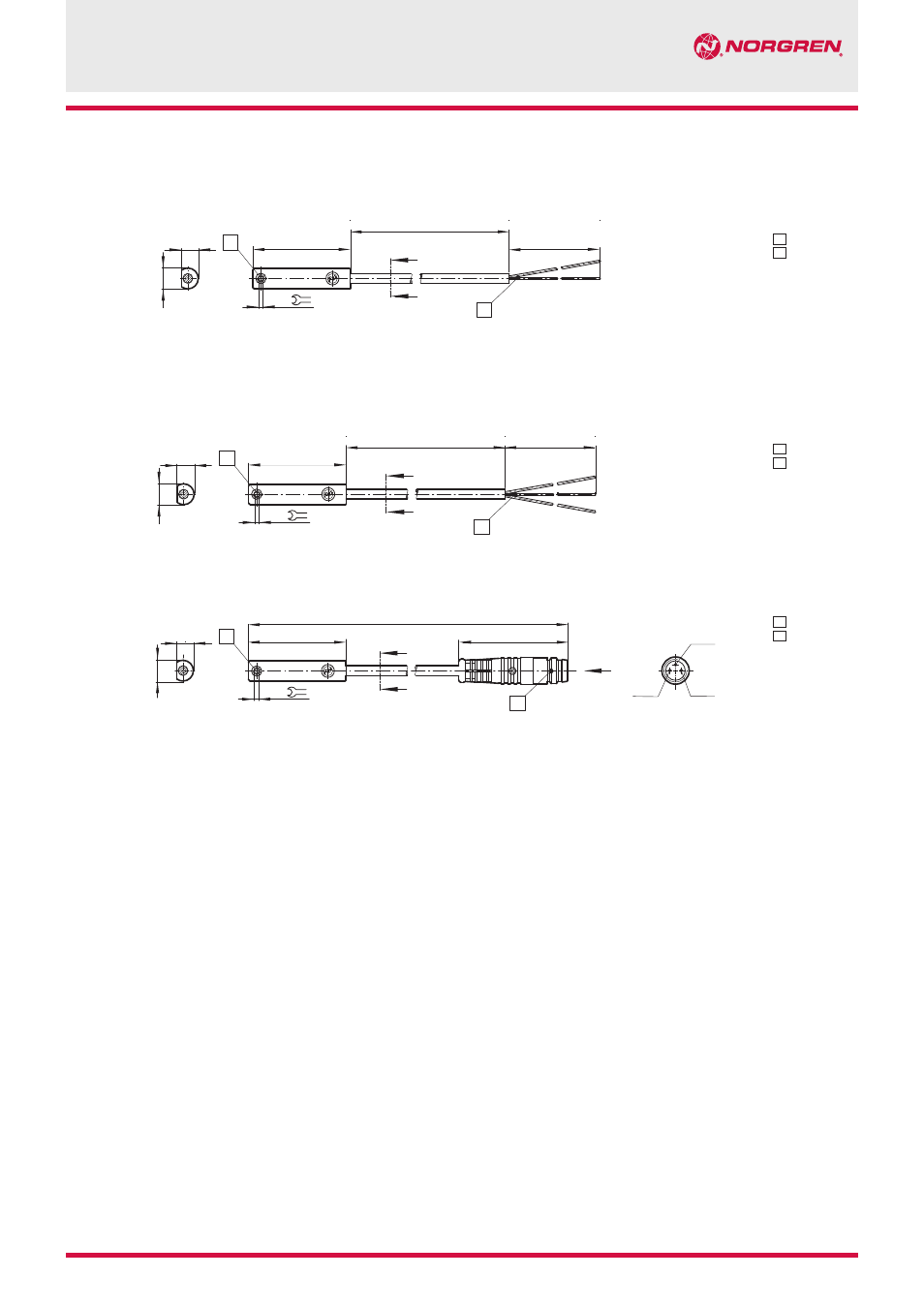
1
Fixing screw
2
+ BN = brown
- BU = blue
(output)
1
Fixing screw
2
- BK = black
+ BN = brown
- ≠BU = blue
1
Fixing screw
3
Plug M8x1
Color code
BK = black
BN = brown
BU = blue
M/50/RAC/5V
Cable length L = 5 m
M/50/LSU/CP
5,1
ø 6,4
30
300
±15
1 BN
3 BU
4 BK
X
A
X
B
A-B
31,5 ... 36
1
3
1,5
5,1
ø 6,4
A
B
A-B
50
+10
L
30
+30
1
1,5
2
5,1
ø 6,4
A
B
A-B
50
+10
L
30
+30
1
1,5
2
Dimensions
M/50/LSU/*V, M/50/LSU/5U, TM/50/RAU/2S
Cable length L = 2, 5 or 10 m