Important, Good better best not recommended – FMI Q431 "Q User Manual
Page 3
result in as much as 20% motor speed reduction
when the pump is operating against a significant
head pressure.
e) THE FLOW STABILITY (precision) of an FMI
PUMP is therefore principally related to consis-
tency in fluid slip rate and stroke repetition rate and
these functions in turn are related to external sys-
tem load factors such as viscosity, differential pres-
sure and electric line voltage; i.e., when load
factors remain essentially constant, slip rate and
repetition rate remain essentially constant; when
viscosity increases, fluid slip rate and stroke repe-
tition rate both decrease; when differential pres-
sure increases fluid slip rate increases and stroke
repetition rate decreases. In short, FMI PUMP
PRECISION is influenced by fluctuations of fluid
differential pressures, fluid viscosity and electric
line voltage. When these factors are controlled pre-
dictably reproducible pumping precision better
than 0.5% may be expected.
MAINTENANCE & REPAIR
INSTRUCTIONS
14. LUBRICATION. Pump drive elements are pro-
vided with oil fittings at all appropriate points. Use
high grade machine oil at regular intervals. A dab
of good grease on PISTON DRIVE PIN just before
it is inserted into the RADIAL BEARING in the
SPINDLE ASSEMBLY does a world of good for the
bearing and pin.
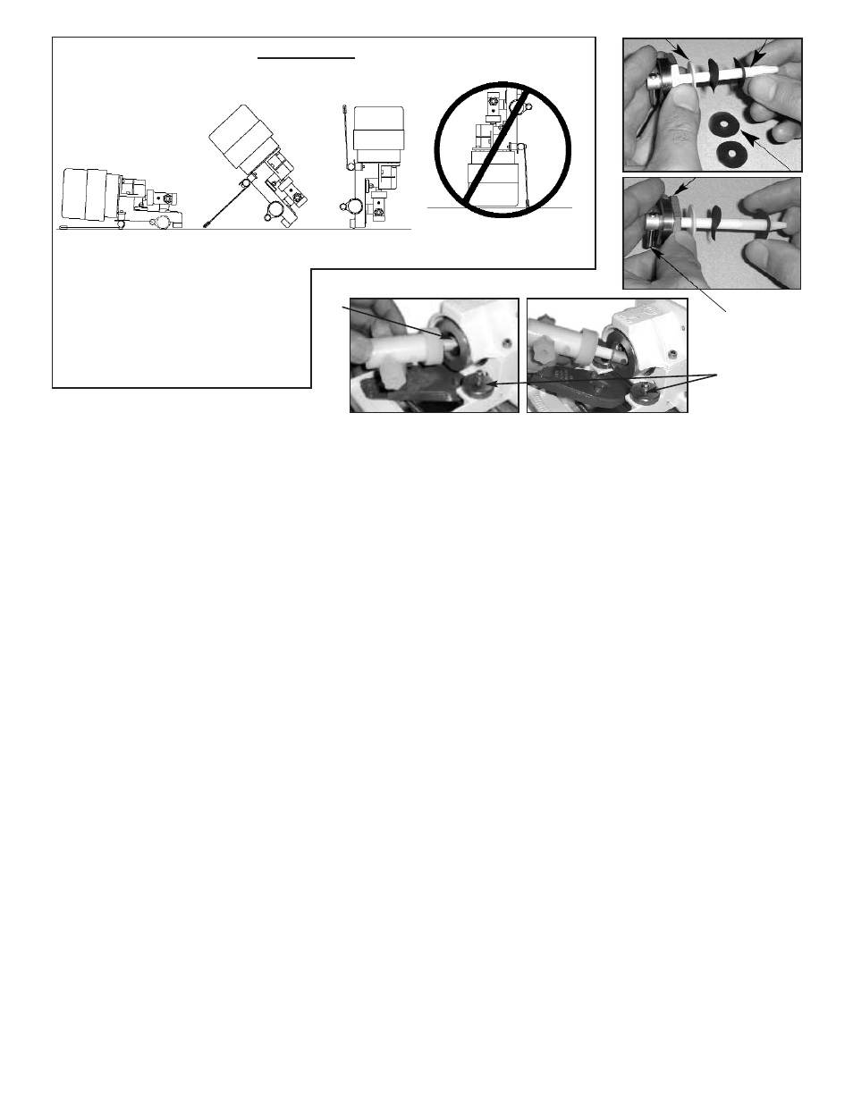
15. CHANGING THE LIQUID END OF YOUR FMI
“Q” PUMP. (figures 1,2).
a) To remove “Q” Pump Head Module (QPHM):
1. Turn power off.
2. Rotate STROKE LENGTH ADJUSTMENT
KNOB to position PUMP HEAD CARRIER Q410-
2 all the way to the extreme right or left of scale
(fig. 1).
3. Rotate SPINDLE ASSEMBLY Q424 to place
PISTON DRIVE PIN at 3 or 9 o’clock position (fac-
ing cylinder head).
4. Loosen two KNURLED NUTS.
5. Lift QPHM and draw gently away from Q424
SPINDLE ASSEMBLY(fig. 2).
6. Move QPHM up and to the left while slipping
DRIVE PIN out of RADIAL BEARING.
b) To replace QPHM:
1. With PISTON ASSEMBLY R423 extending ap-
proximately 1-1/4" from CYLINDER NUT R406K
and DRIVE PIN in the 3 or 9 o’clock position, in-
sert PIN into the RADIAL BEARING in the SPIN-
DLE ASSEMBLY.
2. Slide QPHM into position on BASE making sure
locator on bottom of CARRIER Q410-2 drops into
slotted portion of FOLLOWER Q454-2 on base.
3. Tighten KNURLED NUTS on Q616 assembly
16. CHANGING FITTINGS ON STAINLESS
STEEL PUMP HEADS
IMPORTANT!
Fittings screwed too tightly into stainless steel
pump heads will contact port seals and may cause
piston/cylinder damage. Use extra layers of Teflon
tape on threads when necessary to avoid such ex-
cessive penetration.
17. CLEANING PUMP HEAD. Routine flushing
with solvent before shut-down will suffice for most
applications - set pump for maximum stroke and
operate until solvent appears clear at discharge
port. If periodic teardown for detail cleaning is re-
quired, remove parts with care to avoid damage to
piston, cylinder and gland. Wipe all parts with lint-
less oil saturated cloth. Operate by hand after re-
assembly to assure free movement of parts prior to
application of power.
17.1 CAUTION! Ceramic piston/cylinder sets are
particularly sensitive to neglect and may “freeze”
if allowed to dry out without adequate cleansing.
Some users actually remove the piston from the
cylinder after solvent cleaning and store the com-
ponent parts in disassembled condition until the
pump is again required. Others fill a loop of flexible
tubing with fluid that will thin or neutralize the last
fluid pumped. They then connect one end of the
tube to the pump suction port, the other to the dis-
charge port. With this loop positioned above the
pump head, the ceramic surfaces and seal areas
will stay moist and mobile for extended idle peri-
ods. If, however, a piston (ceramic or stainless
steel) does freeze in the cylinder, DO NOT TRY
TO FORCE IT FREE! Be gentle. Try to remove
the pump head (refer para 15) from the base as-
sembly so that the whole assembly can be soaked
in a suitable solvent. If the head is not conve-
niently removable, the tube loop discussed in the
prior paragraph may permit solvent to dissolve the
“frozen” residue in reasonable time. Having a
spare pump head on hand in case of emergency is
always a good idea.
17.2 SANITARY SERVICE. FMI sanitary pump
heads, designated SAN are designed to conform
with the cleansing standards of the U.S. Food and
Drug Administration.
To clean individual component parts:
a)Unscrew 2 CYLINDER NUTS R406-S and 2
PORT NUTS 110348-P.
b)Remove piston and seal components released
by step a) above;
c)Use fingers to wiggle LINER R407-C slipping it
from CYLINDER CASE R405-SAN;
d)Cleanse and sterilize component parts as per
government regulations for parts manufactured of
Alumina Ceramic, Type 316 Stainless Steel and
Teflon. After cleaning, reassemble the components
as follows:
e)Assemble piston/seal components as per in-
structions para 18 a,b,c;
f)Orient CYLINDER LINER R407-C in CYLINDER
CASE R405-SAN in such a manner that the side
port flats on CYLINDER LINER R407-C should be
visible through the side port openings on CYLIN-
DER CASE R405-SAN.
g)Place one each port seal component R412-T
into each side port of CYLINDER CASE R405-
SAN using finger pressure across the two ports
to assure flush seating of the seal surfaces on
the cylinder liner flats.
h)Apply PORT NUT 110348-P to each port, finger
tight.
i)Carefully insert piston into cylinder liner until
threads of CYLINDER NUT
R406-S meet threads of CYLINDER CASE R405-
SAN. Tighten NUT R406-S finger tight.
Continued on Page 12
3
IN-Q431-09A
For maximum pump performance, mount
the pump with motor at 12 o’clock and
pump head at 6 o’clock position. This ori-
entation will allow air bubbles that enter
the pumping chamber to directly exit thru
buoyant assist. Discharge lines should be
inclined upward from pump head.
IMPORTANT
RECOMMENDED FMI PUMP MOUNTING FOR MAXIMUM
PERFORMANCE
GOOD
BETTER
BEST
NOT
RECOMMENDED
figure 1
figure 2
KNURLED
NUTS
Q424
R408
R409
figure3
figure 4
DRIVE PIN
R423
R406