FMI Q431 "Q User Manual
Page 12
Continued from page 3
j) Place head seal components R413 and R489
into the head end of CYLINDER CASE R405-
SAN, apply CYLINDER NUT R406-S..
k) Wrench tighten each PORT NUT 110348-P 1/6
turn.
l) Wrench tighten each CYLINDER NUT R406-S
1/2 turn, piston end first.
18. PISTON SEAL REPLACEMENT (please see
para 5.) When R408 SEALS are replaced, the
following procedure should be followed: (please
see figs. 3,4)
a) Place GLAND NUT R406 and GLAND
WASHER R409 on PISTON ASSEMBLY R423.
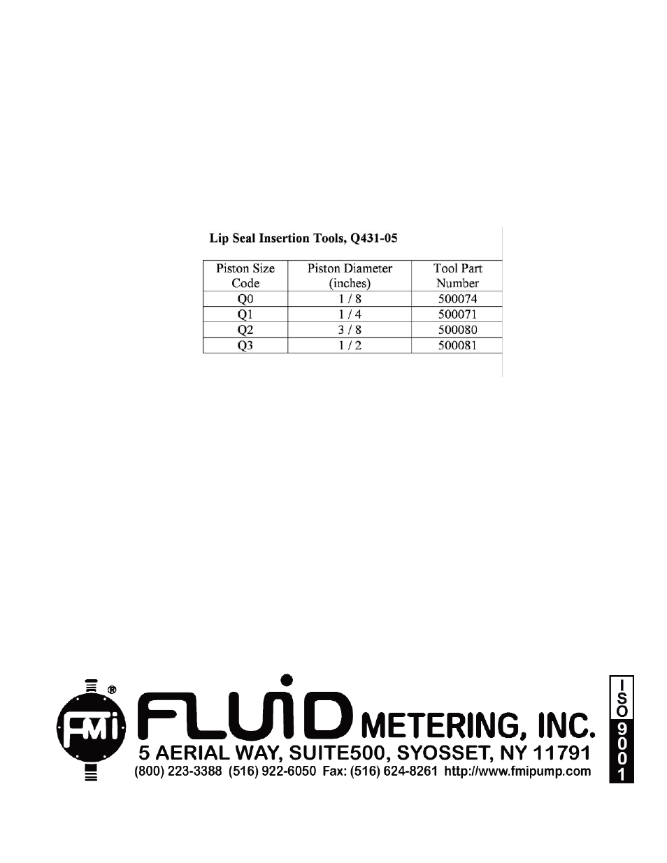
b) Place the lip seal installation tool over the end
of the piston. Slide the tool until piston is seated
in tool. (See lip seal insertion tool table bellow).
c) First “Form” lip of lip seal by gently placing a
lip seal R408 on tool, lip side last. Carefully ro-
tate the seal on the tool while sliding the seal
over the tool’s neck to avoid damage to the lip.
Then remove seal and reverse lip direction
(FIG.3)
d) Gently place one “formed” LIP SEAL R408 on
piston, lip side first, carefully rotating the seal on
the tool until it is past the tool and on the piston
e) Gently place one LIP SEAL R408 on piston,
lip side last. Carefully rotate the seal on the tool
to avoid damage to the lip while passing over the
tool to the piston (fig. 4).
f) Remove installation tool from the piston.
g) Insert piston into cylinder approximately one
inch.
h) Apply GLAND NUT R406 to cylinder threads,
seat gland nut, then tighten to 1/3 turn maximum.
19. PISTON SEAL SETTING. After installing
new
lip seals (part R408) in pump head it is recom-
mended that the seals be set (formed in place)
by fluid pressures generated by pump action. To
accomplish this:
a) Operate the pump spindle clockwise for 10 or
20 strokes at maximum setting, handling water
(left to right mode facing pump head) with suction
line blocked or pinched off. This will create a
vacuum in the pump head, permitting atmos-
pheric pressure to shape the outer seal member
tightly around the piston.
b) Reverse the pumping direction (pump head
angle reversal) and intermittently block the line
leading from the left hand port. This will generate
pressure in the seal area of the pump head,
causing the inner seals to form intimately around
the piston.
12
IN-Q431-09A
WHEN ORDERING REPLACEMENT PARTS PLEASE MENTION MODEL AND SERIAL NUMBERS OF
THE PUMP ON WHICH THEY WILL BE USED.
Record your Model and Serial Numbers below. This will be useful when ordering replacement parts.
PUMP HEAD MODULES (PHM)
PUMP DRIVE MODULE (PDM)
PHM MODEL NUMBER
PHM SERIAL NUMBER
PDM MODEL NUMBER
PDM SERIAL NUMBER
_____________________ QB__________________ _____________________ QA__________________
_____________________ _____________________ _____________________ ____________________
_____________________ _____________________ _____________________ ____________________
_____________________ _____________________ _____________________ ____________________
PLEASE NOTE:
Pistons and cylinders are dimensionally mated. For most satisfactory performance, they should be ordered
as mated sets.