CPI Communications TTP216 Series User Manual
Page 6
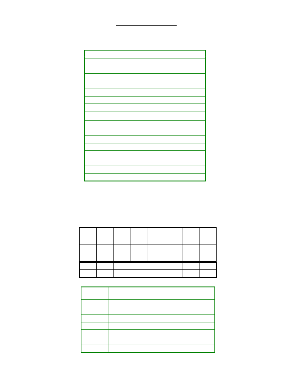
VI. J1 and J2 Configuration Settings
Jumper groups E1-x and E2-x directly enable configuration of the J1 and J2 connectors. Alternatively, connectors E1 and E2 can be manually
wired in any configuration.
jumper
jack
signal
E1-1
J1 - Local Mic
E1-2
J1 - Local Mic
E1-3
J1 - Local Mic
PTT
E1-4
J1 - Local Mic
Mic Audio
E1-5
J1 - Local Mic
Ground
E1-6
J1 - Local Mic
Monitor
E1-7
J1 - Local Mic
E1-8
J1 - Local Mic
E2-1
J2 - Radio
RX Audio
E2-2
J2 - Radio
E2-3
J2 - Radio
PTT
E2-4
J2 - Radio
TX Mod
E2-5
J2 - Radio
Ground
E2-6
J2 - Radio
Monitor
E2-7
J2 - Radio
F1/F2
E2-8
J2 - Radio
VII. Programming
A. Hardware
The programming hardware is located on the right-hand side of the circuit board, and consists of Tone Select pushbutton S1, eight-position DIP
switch S2 and a row of twenty LED's, identified with the numbers 450 through 1950 (EIA Tone LED’s) and the letters A through D (ABCD
LED’s). Functions of the individual S2 DIP switch sections are as follows:
OFF
OFF
OFF
OFF
OFF
OFF
OFF
OFF
ON
ON
ON
ON
ON
ON
ON
ON
TP200 Product Description - 5/23/01 Page 9 of 28
8
7
6
5
4
3
2
1
Y
X
F5
F4
F3
F2
F1
PROG
switch
function
S2-1
Program Mode Enable
S2-2
F1 select
S2-3
F2 select
S2-4
F3 select
S2-5
F4 select
S2-6
F5 select
S2-7
X
S2-8
Y