CPI Communications TTP216 Series User Manual
Page 4
III. Front Panel Indicators
indicator
color
function
PTT
red
PTT on
MON
green
Monitor on
F1
yellow
F1/BCD0 output on (open collector low)
F2
yellow
F2/BCD1 output on (open collector low)
F3
yellow
F3/BCD2 output on (open collector low)
F4
yellow
F4/BCD3 output on (open collector low)
F5
yellow
F5/BCD4 output on (open collector low)
IV. Front Panel Adjustments
adjustment
trimpot
location
function
RX AUD
R105
front panel
adjusts radio RX audio output level to remotes
TX MOD
R106
front panel
adjusts remote audio level to radio TX modulation
input *
MIC AUD
R107
front panel
adjusts local mic level to remotes
LINE AUD
R108
front panel
adjusts remote line audio level for all termination
panel functions *
BALANCE
R104
circuit board
sets hybrid balance of remote line
* adjustment is affected by JP2 setting
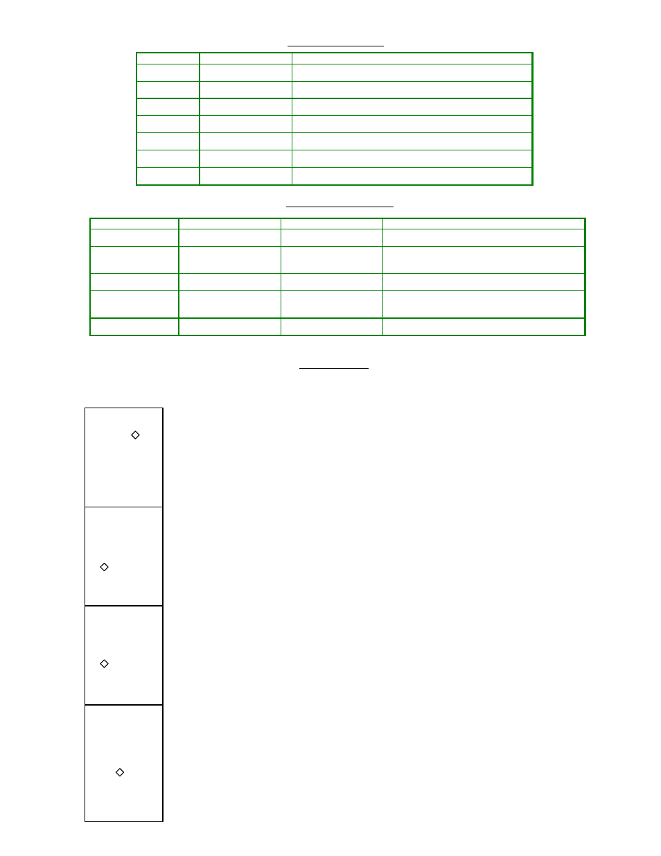
V. Option Settings
Options are selected by setting jumpers. Pin 1 of each jumper group is toward the left side or the back of the board, depending upon its orientation
in the layout. The following descriptions show the position of each jumper on the board when the board is positioned with the front to the bottom
of the illustration.
JP1 2-Wire / 4-Wire Select
Selects remote line interface
1-2
(default) selects 2-wire interface
2-3
selects 4-wire interface
JP2 Line Audio Gain Mode
Selects Manual or Automatic Line Audio Gain
1-2
(default) selects automatic gain control
2-3
selects manual gain control -- use Line Aud (R108) to adjust.
JP3 Mod Out Source Impedance
Selects low or high Mod Out impedance
1-2
(default) selects low impedance (nominal 600 Ohms)
2-3
selects high impedance (47K Ohms)
JP4 Local Mic Audio Gain
Selects gain of the Local Mic amplifier
1-2
(default) selects low gain
2-3
selects high gain