Advantages of cs1601 over l6562, 1 smaller boost inductor, 2 lower total harmonic distortion (thd) – Cirrus Logic AN349 User Manual
Page 2: 3 light load performance, 4 near unity power factor, An349, Figure 2. comparison of thd vs. ac line voltage
AN349
2
AN349REV1
3. Advantages of CS1601 over L6562
The CS1601 uses a revolutionary digital algorithm that has significant advantages over the existing analog CRM-based L6562.
The major advantages are described in the following sections.
3.1 Smaller Boost Inductor
The CS1601 has a digitally implemented variable-frequency, discontinuous conduction mode (VF-DCM) -based algorithm that
permits delivering the same power and the same peak current ratings with a significantly smaller inductance. This results in an
inductor which is considerably smaller in physical dimensions. In the fluorescent ballast application introduced in Section 2, mi-
gration from a L6562-based solution to one using the CS1601 resulted in the inductor being 45% smaller. The same inductor
could be wound with 26% fewer turns or in a smaller core size which would result in a more compact design. The 2x EE19 core
sets used in some L6562-based fluorescent ballasts could be replaced with a single EE25 inductor reducing the total cost and
size of the final solution.
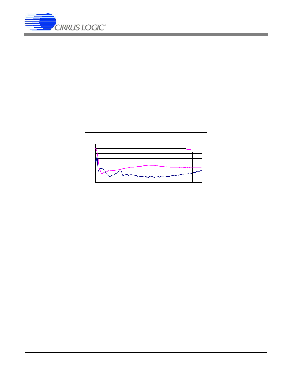
3.2 Lower Total Harmonic Distortion (THD)
The CS1601-based design has lower THD than the L6562-based solution. In the fluorescent ballast example, it can be seen that
the THD across the line at full load was more than 2.5% lower than L6562 as shown in Figure 2.
Figure 2. Comparison of THD vs. AC Line Voltage
The L6562 cannot support large differential filter capacitors on the DC side of the bridge rectifier. In CRM controllers, the maxi-
mum switching frequency at the trough of the AC line is theoretically infinity. The L6562 sets a limit on this maximum, increasing
distortion of the AC line when a larger capacitor is placed across the rectified (DC) AC line. The L6562-based ballast necessitates
expensive AC capacitors placed on the AC line side of the bridge rectifier, increasing the cost of the EMI filter. Since the THD in
the CS1601-based solution is significantly lower, it allows the designer to reduce the EMI filter cost by moving a substantial por-
tion of the differential filter capacitance to the DC side of the bridge rectifier. This eliminates the need for expensive AC capacitors
and reduces overall bill of material (BOM) cost.
3.3 Light Load Performance
The flexibility of moving filters to either side of the rectifier also offers another significant advantage over the L6562 with respect
to light-load PF and high-line-voltage THD. In traditional analog solutions, placing capacitors at the output of the bridge rectifiers
increases THD, especially at light-load conditions and high line voltage. At the trough of the AC line, CRM controllers run at very
high frequencies and switch intermittently to limit switching losses. Placing capacitors at the input side of the bridge reduces PF
since the EMI capacitor swings to twice the input voltage. Power supply designers have to make trade-offs between light load
efficiency, power factor, and THD. The L6562 has errors and delays resulting from the multiplier, comparator, and gate drivers.
These result in errors in peak current at light loads. In the trough these cause significant deterioration of THD performance. As a
workaround to this problem, traditional CRM controllers have to greatly increase the inductance of the boost inductor to limit the
slope of the current and limit the error in peak current that is caused. Since the CS1601 is a variable-frequency DCM controller
with different frequency profile, the limitations encountered when using the L6562 are not present in a system designed with the
CS1601. The CS1601 offers optimal performance with minimal design constraints.
3.4 Near Unity Power Factor
Improved THD performance necessitates large AC capacitors for differential mode EMI filters. Because the voltage swing on ca-
pacitors on the AC line side of the bridge rectifier is twice that of the capacitors placed on the DC side of the bridge, power factor
is reduced. Figure 3 compares the PF between the L6562-based ballast and the CS1601-based ballast. The CS1601 maintains
THD Vs Line @ 60Hz
0
2
4
6
8
10
12
14
16
80
100
120
140
160
180
200
220
240
260
280
300
Line Voltage (V)
% TH
D
CS1601
ST L6562