2 ifb - pin 1, Conclusion, An349 – Cirrus Logic AN349 User Manual
Page 13
AN349
AN349REV1
13
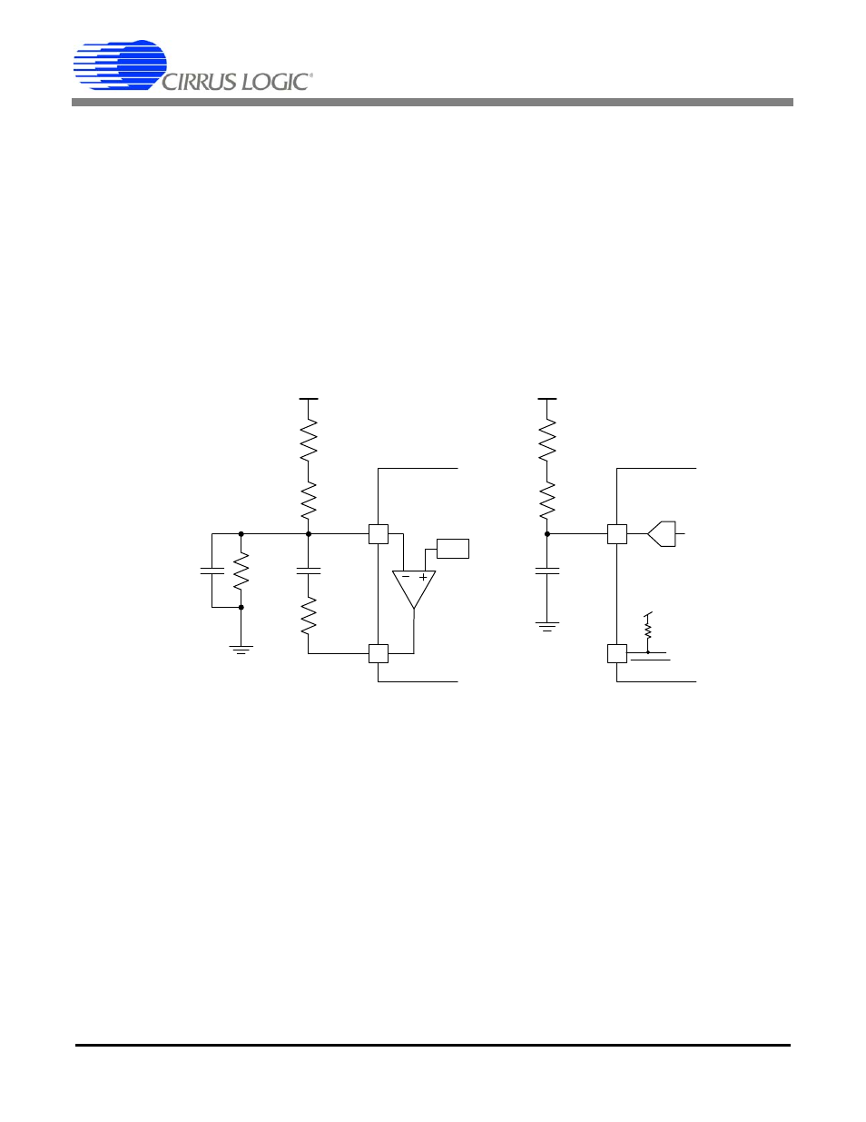
6.6.2 IFB - Pin 1
The filter pole (corner) on pin 1 is calculated by:
Fp = 1
(2
R
fb
C
fb
2
Gain)
From the L6562 data sheet, we will set the gain of the op-amp to 60 dB at DC, which results in a very low corner frequency. The
CS1601 does not require this low corner frequency created by the feedback components. The following changes should be made
when using the CS1601:
-
C
fb
1, C
fb
2, R
fb
3, and R
fb
4 are removed.
-
R
fb
1 and R
fb
2 are changed to the appropriate value to get the required link voltage (1.75M
for V
link
= 460V)
-
C
fb
is added to provide noise filtering on the IFB pin.
The internal impedance of the IFB pin is the same as pin IAC (~12k
), so it is recommended that the capacitor value be the same
as used on pin IAC.
Figure 16. Output Voltage (DC) Sense Noise De-coupling
7. Conclusion
It has been shown that there are significant benefits from selecting the CS1601 over the L6562. The advantages were demon-
strated in an equivalent comparison by retrofitting an existing ballast product designed with the L6562 with the CS1601.
When using the CS1601, care should be taken to adequately protect the device from noise through the use of decoupling capac-
itors & careful layout. The value of the capacitors should be also considered.
C
fb
1
L6562
INV
R
fb
2
R
fb
1
C
fb
2
V
link
R
fb
3
COMP
1
2
V
ref
R
fb
4
CS1601
IFB
R
fb
2
R
fb
1
C
fb
V
link
1
2
V
DD
600 k
ADC
STBY