Pin descriptions, Cs6422 – Cirrus Logic CS6422 User Manual
Page 42
CS6422
42
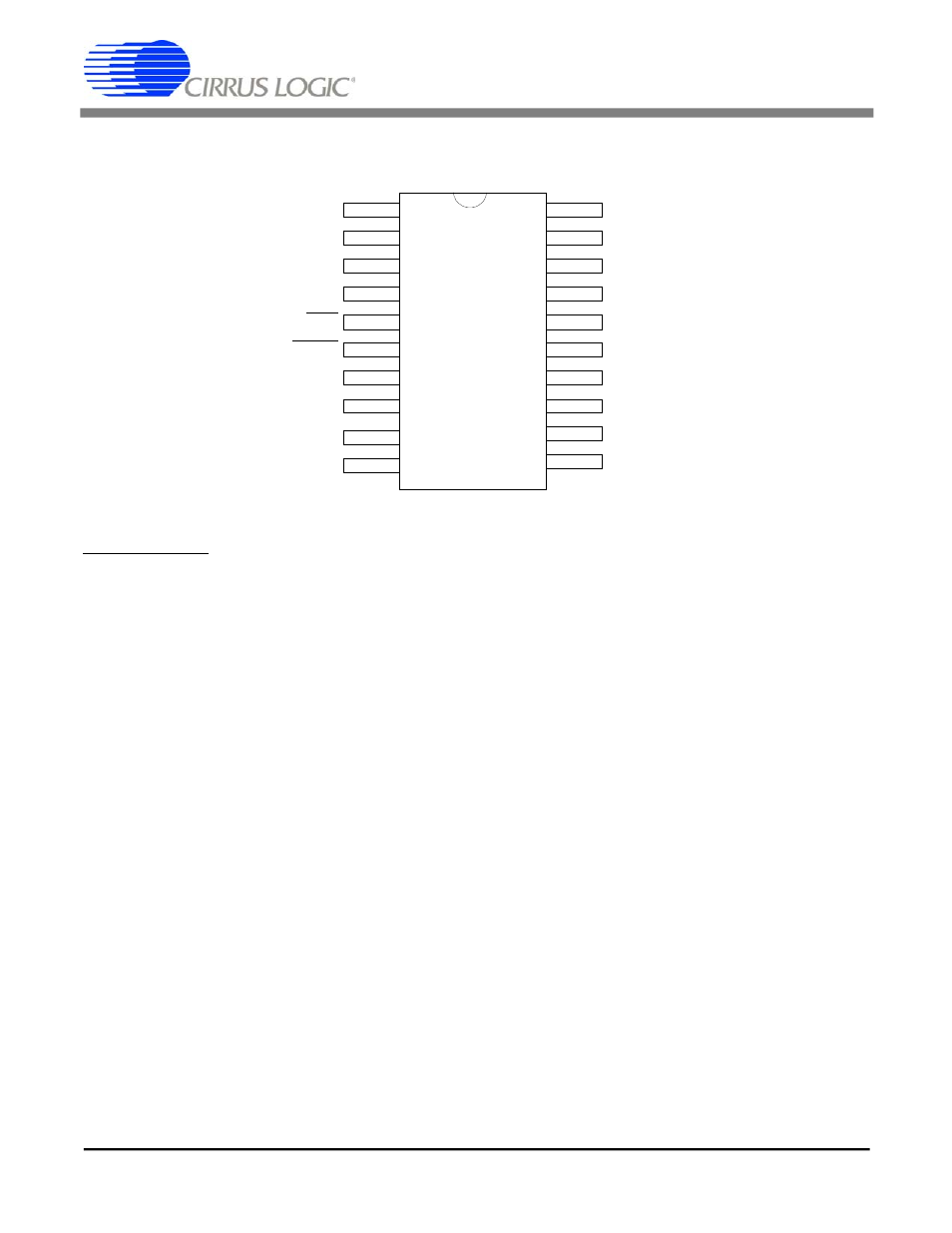
5. PIN DESCRIPTIONS
Analog Interface
AO - Acoustic Interface Output, Pin 3
Analog voltage output for the acoustic side (near-end output/receive output). Maximum output signal is
1.1 V
rms
(3.1 V
pp
). This output can drive down to 10 k
Ω and is usually followed by a speaker driver. The
output is pre-compensated to expect a single-pole RC low pass filter with a corner frequency of 4 kHz.
NO - Network Interface Output, Pin 4
Analog voltage output for the network side (far-end output/transmit output). Maximum output signal is
1.1 V
rms
(3.1 V
pp
). This output can drive down to 10 k
Ω. The output is pre-compensated to expect a
single-pole RC low pass filter with a corner frequency of 4 kHz.
API - Acoustic Interface Preamplifier Input, Pin 20
Input to the acoustic side microphone preamplifier. Signal source resistance at this pin will reduce the
34 dB gain inherent in the preamplifier. The maximum input signal level to avoid clipping is 20 mV
rms
(57 mV
pp
), assuming default settings.
APO - Acoustic Interface Preamplifier Output, Pin 18
Output of the acoustic side microphone preamplifier and input to the acoustic side analog-to-digital
converter (near-end input/transmit input). This input expects a single-pole RC anti-aliasing filter with a
corner frequency of 8 kHz. Maximum signal level before clipping at this point is 0.9 V
rms
(2.5 V
pp
),
assuming default settings for TGain.
MB - Microphone Bias Voltage Output, Pin 19
Output of 3.5 VDC provides the internal voltage reference for the CS6422. MB must be decoupled with
a 10
µF and 0.1 µF capacitor to prevent noise from affecting the on-chip voltage reference. MB must
not be connected to any load.
1
2
3
4
5
6
7
8
12
13
14
15
16
AVDD
AGND
AO
NO
RST
DRDY
STROBE
DATA
DVDD
DGND
CLKI
CLKO
NC4
9
10
NC1
NC2
17
18
APO
NI
19
20
API
MB
11
NC3
CS6422
CS6422
42
DS295F1