11 power supply, Figure 8. suggested layout, 1 power down mode – Cirrus Logic CS6422 User Manual
Page 30: 2 noise and grounding, 1 power down mode 3.11.2 noise and grounding, Cs6422
CS6422
30
3.11
Power Supply
The pins AVDD (pin 1) and AGND (pin 2) power
the analog sections of the CS6422, and DVDD (pin
16) and DGND (pin 15) power the digital sections.
This distinction is important because internal to the
part, the digital power supply is likely to contain
high-frequency energy. The analog power supply is
kept clean internally by drawing current from a dif-
ferent pin, thereby achieving high performance in
the codecs and the microphone preamplifier.
The digital supply of the CS6422 should not be
connected to the system digital supply, if there is
one, as the CS6422 has internal timing mechanisms
designed to minimize the detrimental effects of its
own digital noise, but cannot use these to compen-
sate for externally introduced digital noise. The
CS6422 digital power supply should be derived
from its analog power supply through a ferrite bead
with low (< 1
Ω) DC impedance.
3.11.1
Power Down Mode
Typical power consumption of the CS6422 is
60 mA, assuming normal operating conditions.
This current consumption can be further reduced
by invoking the powerdown mode, which is en-
tered by holding RST low. Holding RST low will
power down all the internal blocks of the CS6422
and stop the oscillator. In powerdown mode, cur-
rent consumption drops to less than 2 mA.
3.11.2
Noise and Grounding
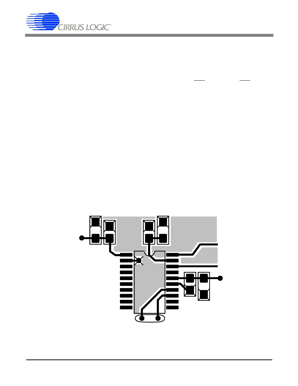
Since the CS6422 is a mixed-signal integrated cir-
cuit, the system designer must pay special attention
to layout and decoupling to minimize noise cou-
pling. The three best methods to reduce noise when
using the CS6422 are to properly decouple the
power supplies, to separate the system analog and
digital power and ground (all power and ground
pins of the CS6422 should tie to the analog power
supply), and to route signals on the board carefully.
AGND
DVDD
MB
AVDD
+5V
Analog
Supply
DGND
From
Ferrite
Bead
Figure 8. Suggested Layout
CS6422
30
DS295F1