Figure 9. ground planes, Cs6422 – Cirrus Logic CS6422 User Manual
Page 31
CS6422
31
Figure 8 shows the suggested placement of decou-
pling capacitors for the power supplies. Note that
the trace length from the power pin to the capaci-
tors is minimized. Also note that the smaller valued
capacitor is placed closer to the pin than the larger
valued capacitor. The smaller capacitor decouples
high frequency noise and the larger capacitor atten-
uates lower frequencies.
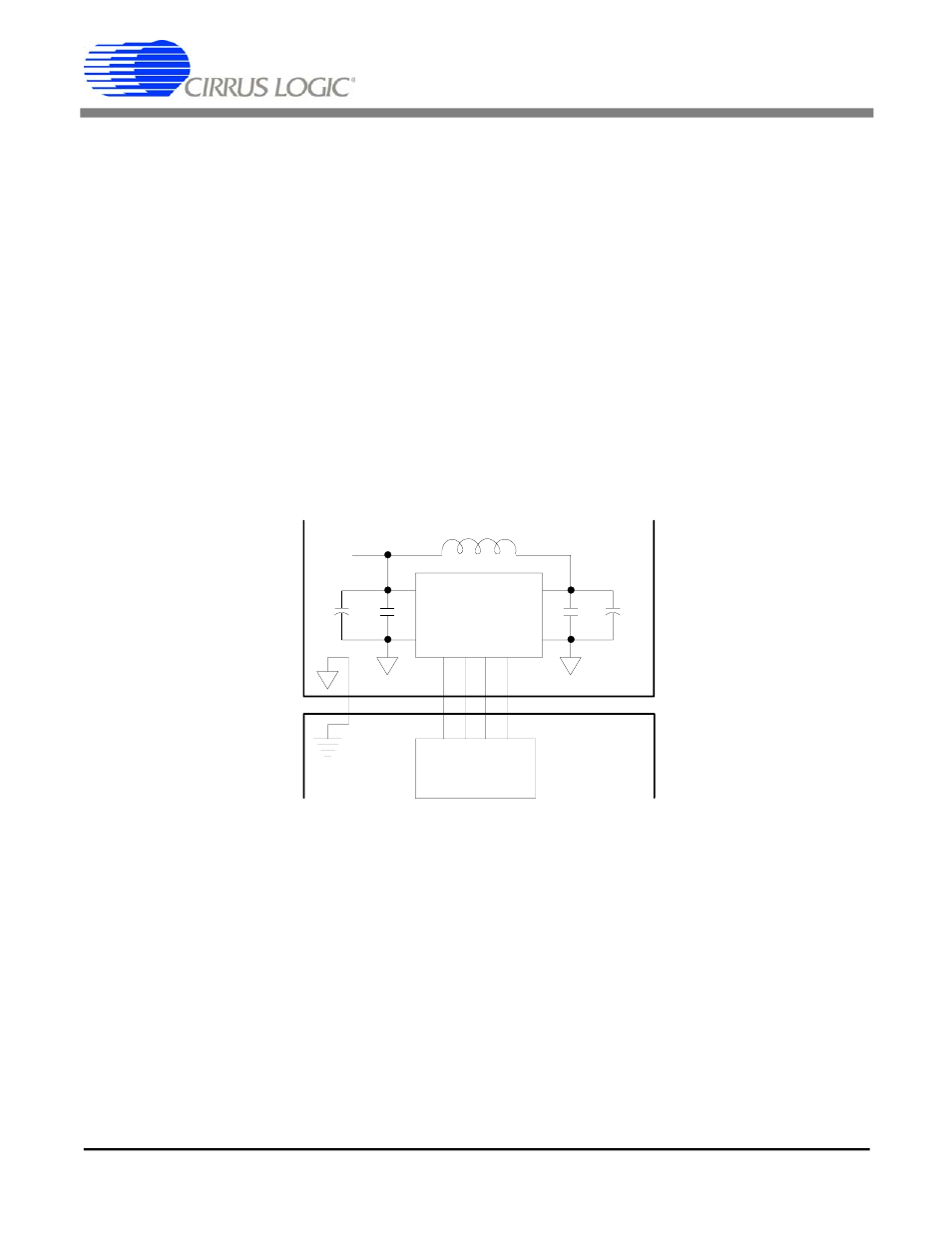
The separation of analog and digital power and
ground is done in two ways. The power is separated
by deriving the digital power for the CS6422 from
the analog through a ferrite bead to isolate analog
from digital, as shown in Figure 9. The ferrite bead
serves as a low-pass filter to remove CS6422 digi-
tal switching noise from the analog power supply.
The ground is separated by isolating all the digital
components of the system board on one ground
plane and all the analog and linear components on
a different ground plane. The CS6422 should be
placed over the analog ground plane. This prevents
digital switching noise from the digital components
of the board from coupling into the converters and
aliasing into the passband.
+5V
(Analog)
AVDD
AGND
DVDD
DGND
Analog Ground Plane
Digital Ground Plane
Microcontroller
10
µF 0.1 µF
0.1
µF 10 µ F
Ferrite Bead
CS6422
Figure 9. Ground Planes
CS6422
DS295F1
31