An44rev2 5 – Cirrus Logic AN44 User Manual
Page 5
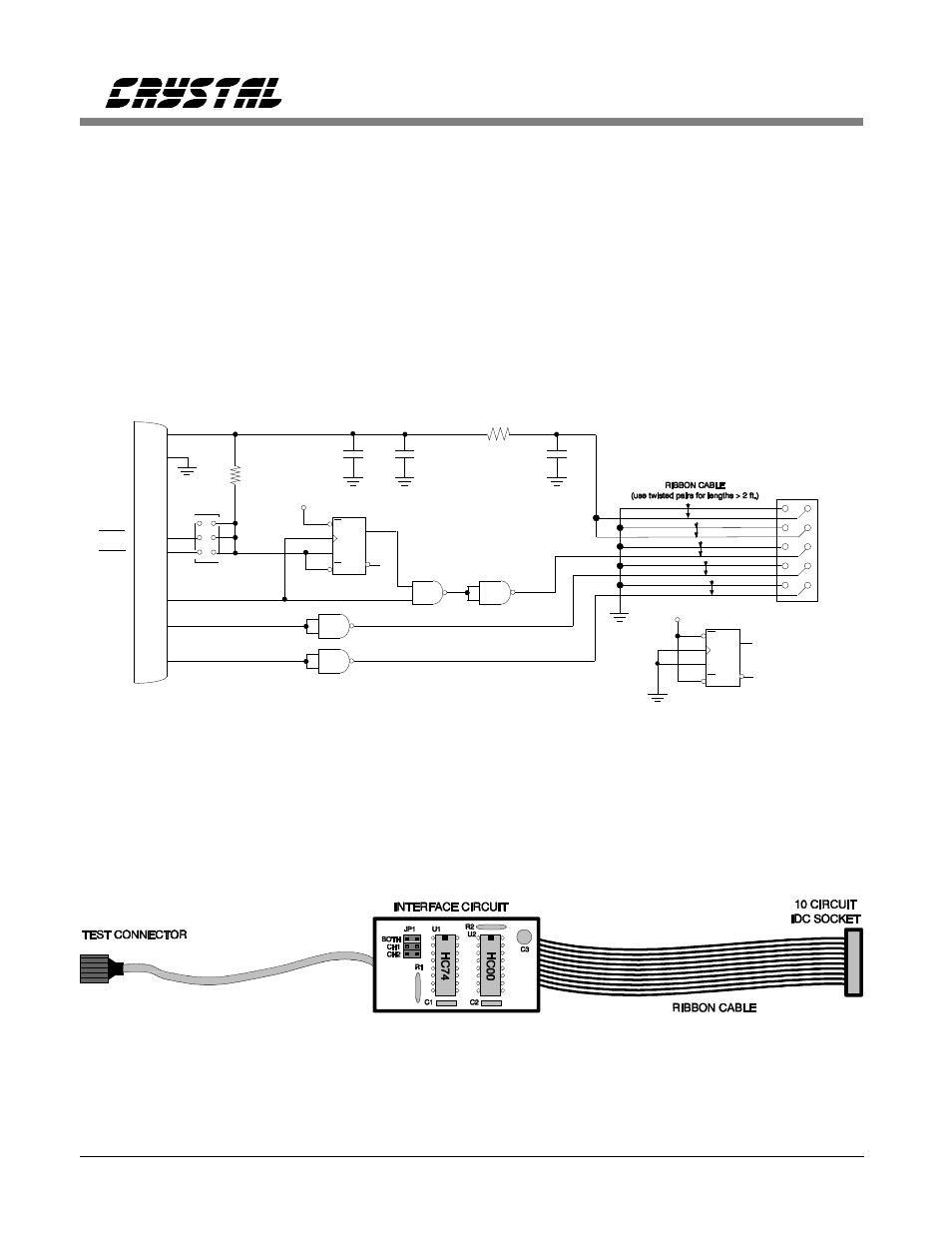
Figures 4, 5 and 6. The digital interface circuitry
for the CS5102A is show in Figure 5.
Figure 6 is the way the digital circuitry is
implemented on the modified serial cable.
Figure 7 is the hardware implementation of the
modified serial cable shown in Figure 6. In this
example, the embedded system is designed with
a test connector. The modified serial cable is
built with a connector which mates to the system
test connector. The test connector provides a
convenient and reliable means of interfacing the
ADC.
U2-C
3
1
2
U2A
8
9
10
11
12
13
+5V
U3B
R1
10k
JP1
BOTH
CH2
CH1
Q
D
S
R
P2
+ C3
10
µ
F
+5V
+5V
SLATCH
SCLK
SDATA
U2-B
U2B
10
R3
+ C2
0.1
µ
F
+ C1
0.1
µ
F
4
5
6
8
10
9
11
13
12
SDATA
SCLK
+5V
SSH/SDL
TRK2
TRK1
GND
P1
74HC00
74HC74
6
5
4
3
2
1
+5V
U3A
Q
D
S
R
Figure 6. Modified Serial Cable Implementation of the Digital Interface
Figure 7. Construction of the Modified Serial Cable
Using The CDBCapture System with Embedded A/D Converters
AN44REV2
5
- CobraNet (147 pages)
- CS4961xx (54 pages)
- CS150x (8 pages)
- CS1501 (16 pages)
- CS1601 (2 pages)
- CS1601 (16 pages)
- CS1610 (16 pages)
- CRD1610-8W (24 pages)
- CRD1611-8W (25 pages)
- CDB1610-8W (21 pages)
- CS1610A (18 pages)
- CDB1611-8W (21 pages)
- CDB1610A-8W (21 pages)
- CDB1611A-8W (21 pages)
- CRD1610A-8W (24 pages)
- CRD1611A-8W (25 pages)
- CS1615 (16 pages)
- AN403 (15 pages)
- AN401 (14 pages)
- AN400 (15 pages)
- AN375 (27 pages)
- AN376 (9 pages)
- CRD1615-8W (22 pages)
- CRD1616-8W (23 pages)
- AN402 (14 pages)
- AN404 (15 pages)
- CRD1615A-8W (21 pages)
- CS1615A (16 pages)
- CS1630 (56 pages)
- AN374 (35 pages)
- AN368 (80 pages)
- CRD1630-10W (24 pages)
- CRD1631-10W (25 pages)
- CS1680 (16 pages)
- AN405 (13 pages)
- AN379 (31 pages)
- CRD1680-7W (31 pages)
- AN335 (10 pages)
- AN334 (6 pages)
- AN312 (14 pages)
- AN Integrating CobraNet into Audio Products (16 pages)
- CobraNet Audio Routing Primer (9 pages)
- Bundle Assignments in CobraNet Systems (3 pages)
- CS2300-01 (3 pages)
- CS2000-CP (38 pages)