Cirrus Logic AN44 User Manual
Page 4
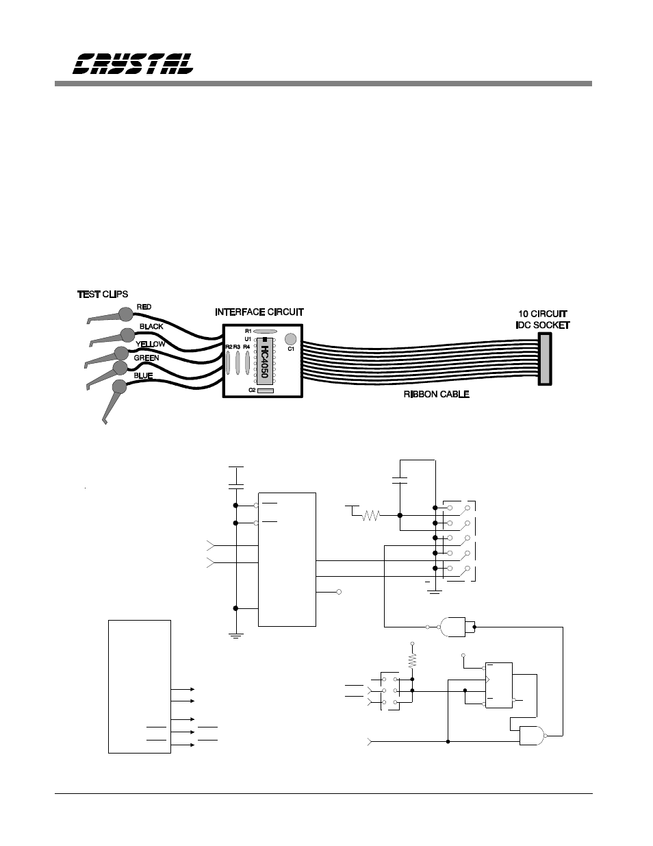
Figure 4 shows how the hardware can be
implemented. The digital interface circuitry is
built upon a small circuit board. A ribbon cable
with a 10 circuit IDC socket is used for the
CDBCAPTURE interface. Separate ground wires
should be used for each signal return, and
twisted pair ribbon cable used for lengths greater
than two feet. The embedded interface uses
color coded test clips. The test clips provide a
means of interfacing an ADC without any
special connectors designed in the system.
However this method requires a little more setup
time, since the appropriate signals need to be
located on the circuit board.
CS5102A EXAMPLE
The CS5102A is used in the second example of
an embedded application. The methodology for
the cable design is the same as that in the first
example using the CS5508. The digital interface
circuitry is obtained from the CDB5101A/5102A
evaluation board data sheet. This information is
contained in the evaluation board’s data sheet
Figure 4. Construction of the Modified Serial Cable
TP00
U2
9
10
8
6
4
5
U2
CLK
74HC74
8
9
10
11
12
13
+5V
U3
1
2
3
4
5
6
+5V
R16
10k
JP4
HDR8D
TRK1
TRK2
SSH/SDL
BOTH
CH2
CH1
Q
D
S
R
OE1
OE2
Y0
Y2
Y5
74HC365
3
7
13
2
6
14
1
15
U12
.1 uF
C48
+5V
A0
A2
A5
HDR10D
+5V
JP5
10
R3
+
C47
10 uF
SDATA
SCLK
+5V
+5V
SLATCH
SCLK
SDATA
SSH/SDL
U1
CS5101A
or
CS5102A
SSH/SDL
TRK1
TRK1
TRK2
TRK2
SCLK
SCLK
SDATA
SDATA
Figure 5. CDB5102A Evaluation Board Schematic for the Digital Interface
Using The CDBCapture System with Embedded A/D Converters
4
AN44REV2