Cirrus Logic CDB5464U User Manual
Features, General description
Copyright
© Cirrus Logic, Inc. 2007
(All Rights Reserved)
CDB5464U
CDB5464U Engineering Board and GUI Software
Features
Voltage and Current Interface
USB Communication with PC
On-board C8051F320 Microcontroller
On-board Voltage Reference
LabWindows
®
/CVI
®
GUI Software
– Register Setup & Chip Control
– FFT Analysis
– Time Domain Analysis
– Noise Histogram Analysis
"Auto-boot" Demo with Serial EEPROM
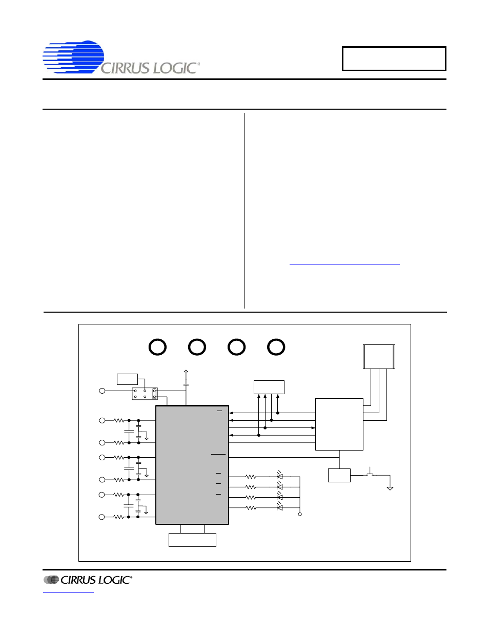
General Description
The CDB5464U is an inexpensive tool designed to evaluate
the functionality and performance of the CS5464 analog-to-dig-
ital converter (ADC). The evaluation board includes an LT1019
voltage reference, a C8051F320 microcontroller with a USB in-
terface, and firmware. The microcontroller controls the serial
communication between the evaluation board and the PC via
the firmware, enabling quick and easy access to all of
theCS5464's registers and functions.
The CDB5464U includes software for data capture, time do-
main analysis, histogram analysis, and frequency domain
analysis.
Schematics in PADS™ PowerLogic™ format are available for
download at
ORDERING INFORMATION
CDB5464U
Evaluation Board
OCT ‘07
DS847DB1
CS5464
C8051F320
+2.5V
reference
USB
Reset
Circuirty
SERIAL
EERPOM
RESET
BUTTON
CS
SDI
SDO
SCLK
INT
RESET
E1
E2
E3
MODE
REF
+5V
GND
VD+_EXT
Vu+_EXT
IN OUT
VREF
4.096MHz
Crystal
IIN1+
IIN1-
IIN2+
IIN2-
VIN+
VIN-
Document Outline
- Features & Description
- Table of Contents
- List of Figures
- 1. Hardware
- 2. Software
- 2.1 Installation
- 2.2 Using the Software
- 2.3 Start-up Window
- 2.4 Setup Window
- 2.4.1 Refresh Screen Button
- 2.4.2 Reset DUT Button
- 2.4.3 CS5464 Crystal Frequency
- 2.4.4 Configuration Register
- 2.4.5 Control Register
- 2.4.6 Mask Register / Status Register
- 2.4.7 Mode Control Register
- 2.4.8 Cycle Count / Pulse Output Registers
- 2.4.9 Voltage Sag / Current Fault / Ichanlevel / Emin (Irmsmin) / VFrms / Tsettle / LoadMIN / Epsilon / Temperature Registers
- 2.5 Calibration Windows
- 2.6 Conversion Window
- 2.7 Pulse Rate Window
- 2.8 Data Collection Window
- 2.8.1 Time Domain / FFT/ Histogram Selector
- 2.8.2 Config Button
- 2.8.3 Collect Button
- 2.8.4 Output Button
- 2.8.5 Zoom Button
- 2.8.6 Channel Select Button
- 2.8.7 Configuration Window
- 2.8.8 Collecting Data Sets
- 2.8.9 Retrieving Saved Data From a File
- 2.8.10 Analyzing Data
- 2.8.11 Histogram Information
- 2.8.12 Frequency Domain Information
- 2.9 EEPROM Window
- 2.10 Debug Panel
- Appendix A. Bill Of Materials
- Appendix B. Schematics
- Appendix C. Layer Plots
- Revision History