System overview, 1 dc power supplies, 2 voltage sensor – Cirrus Logic CRD5463PM User Manual
Page 3: Crd5463pm
CRD5463PM
DS805RD2
3
2. SYSTEM OVERVIEW
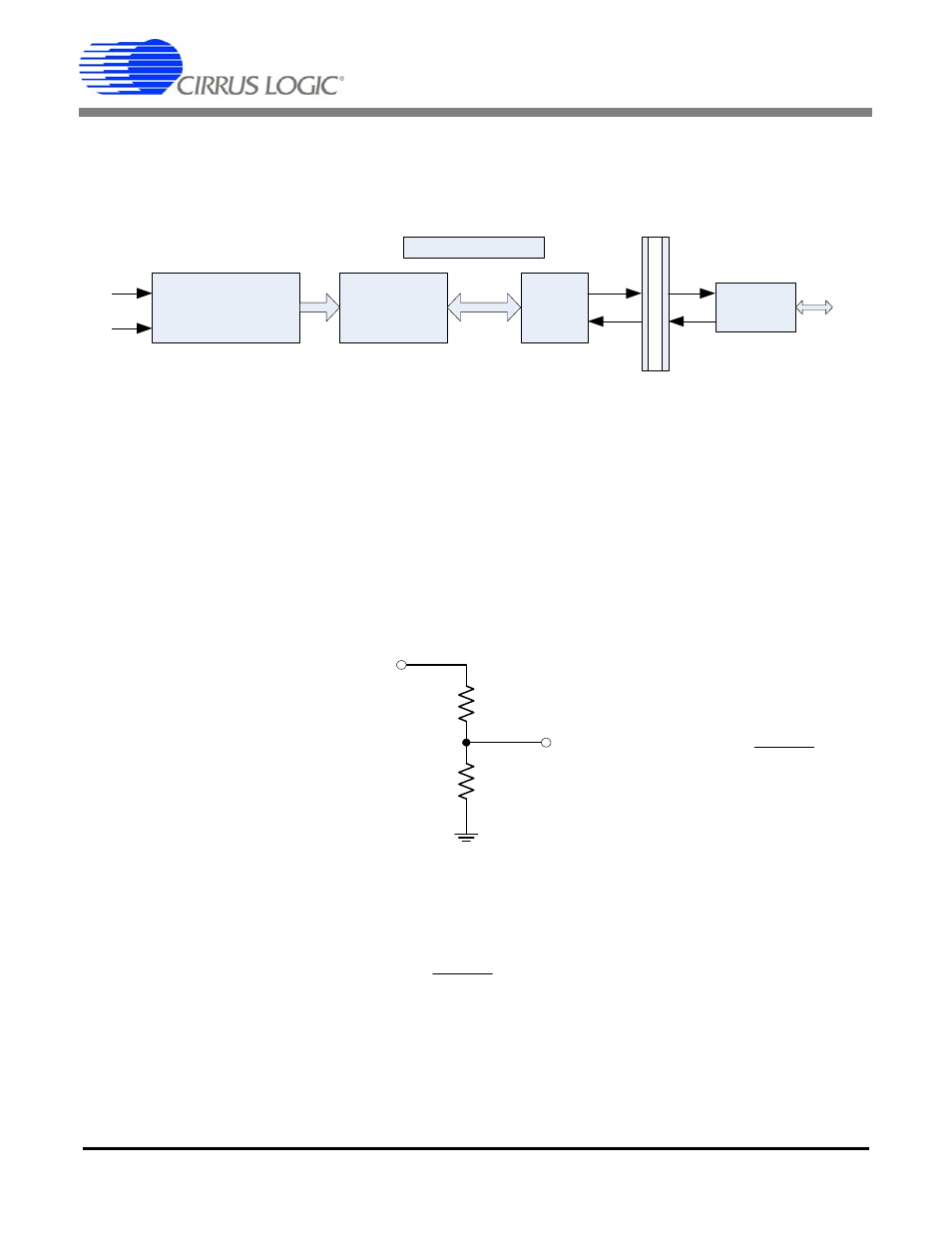
As illustrated in Figure 1, the CRD5463PM is composed of voltage and current sensors, a CS5463 power
measurement device, an ATtiny2313 microcontroller, opto-coupler isolation, and UART-USB converter.
Figure 2. CRD5463PM Simplified Block Diagram
2.1 DC Power Supplies
There are two isolated +5V DC power domains in the CRD. One is converted from AC power lines through
capacitor-dropper AC/DC power supply and provides +5VDC supply to the CS5463 and MCU. The other
is directly from PC through USB interface and provides +5VDC to the UART-USB converter.
This capacitor type of DC power supply is very low-cost but not efficient. Total power consumption drew
from the AC line is 2.3 Watt and 79mA (tested with 240 VAC input).
2.2 Voltage Sensor
The high AC line voltage must be converted to small voltage signal before being applied onto the CS5463
voltage channel inputs (VIN±). The CRD5463PM uses resistor voltage divider as the voltage sensor.
Figure 3. CRD5463PM Resistive Divider Voltage Sensor
The divider ratio is determined by the maximum V
in
and the maximum input range of the CS5463 voltage
channel. The maximum input range of the CS5463 voltage channel is 176 mV RMS. The division ratio
shall be chosen to satisfy the equation:
To leave some margin, the Vout is normally set around 150 mVrms with the maximum V
in
. In the
CRD5463PM, R2 is 1 k
Ω. R1 is composed of four 422 kΩ resistors to increase the total voltage rating of
the voltage sensor.
When V
in
= 260 V RMS, V
out
= 260 V Ч 1 / [1 + (4 Ч 422)] = 154 mV RMS.
Voltage & Current
Sensors
CS5463
Power
Measurement
MCU
UART -
USB
SPI
Reset
Interrupt
UART
V
I
AC/DC
UART
Is
ol
a
tio
n
U
S
B
R
2
Vout
R
1
Vin
2
1
2
R
R
R
Vin
Vout
+
×
=
mVrms
R
R
R
Vin
176
2
1
2
max
<
+
Ч