Section 3.14, Cs5460a – Cirrus Logic CS5460A User Manual
Page 37
CS5460A
DS487F5
37
performed on each individual power meter, during
final calibration/test of the meter.
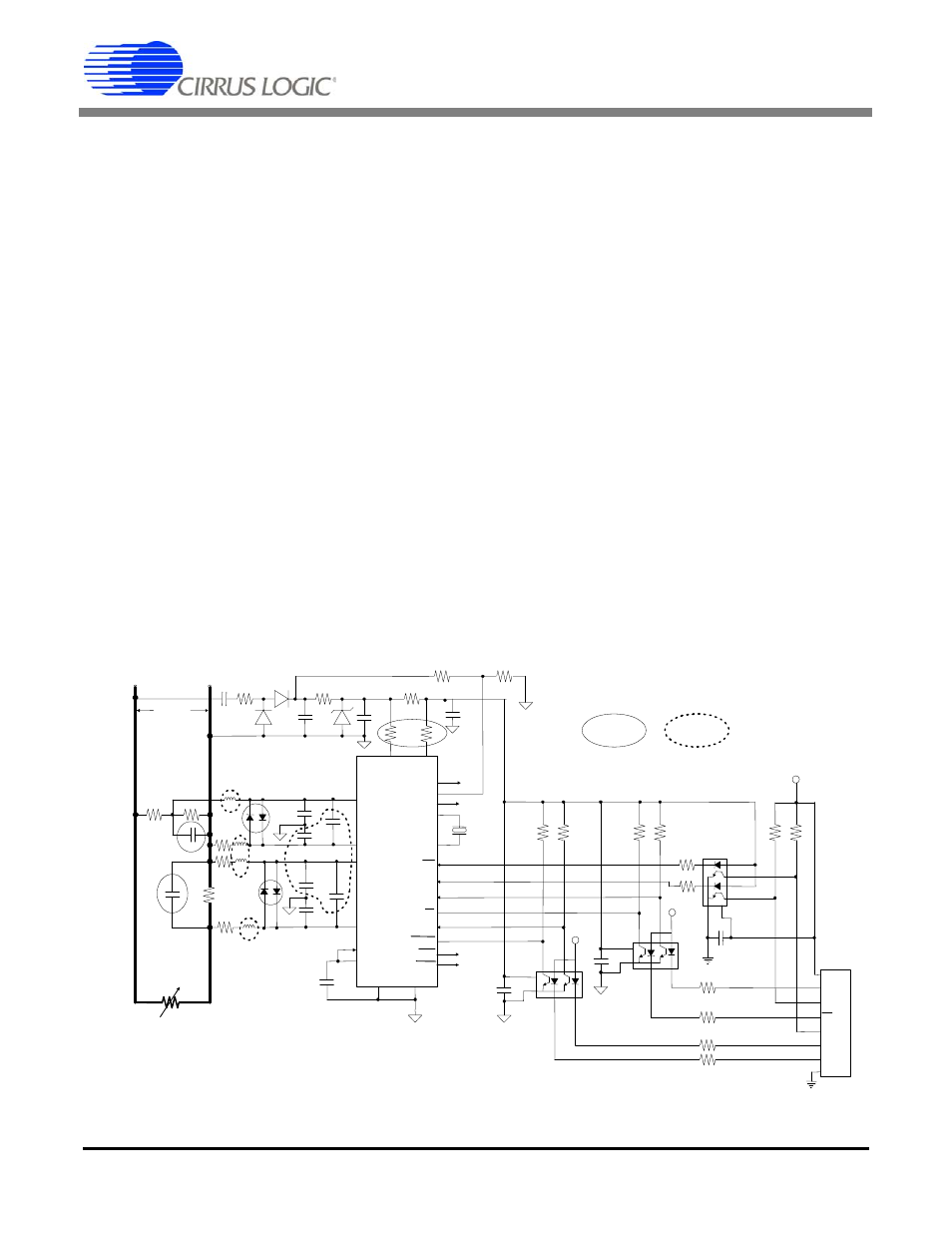
3.14 Protection Against High-voltage
and/or High-current Surges
In many power distribution systems, it is very likely
that the power lines will occasionally carry brief but
large transient spikes of voltage/current. Two com-
mon sources of such high-energy disturbances are
1) a surge in the line during a lightning storm, or 2)
a surge that is caused when a very inductive or ca-
pacitive load on the power line is suddenly turned
on (“inductive kick”). In these situations, the input
protection resistors and corresponding input filter
capacitors (discussed in the previous sections)
may not be sufficient to protect the CS5460A from
such high-frequency voltage/current surges. The
surges may still be strong enough to cause perma-
nent damage to the CS5460A. Because of this, the
designer should consider adding certain additional
components within the voltage/current channel in-
put circuitry, which can help to protect the
CS5460A from being permanently damaged by the
surges.
Referring to Figure 20, the addition of capacitors
C1 and C2 can help to further attenuate these
high-frequency power surges, which can greatly
decrease the chances that the CS5460A will be
damaged. Typical values for C1 and C2 may be on
the order of 10 pF, although the exact value is re-
lated to the reactive and resistive properties of the
voltage and current sensor devices. In addition, di-
odes D1 - D4 can help to quickly clamp a high volt-
age surge voltage presented across the
voltage/current inputs, before such a surge can
damage the CS5460A. An example of a suitable
diode part number for this application is BAV199,
which has the ability to turn on very quickly (very
small turn-on time). A fuse could potentially serve
this purpose as well (not shown). R3 and R4 can
provide protection on the “-” sides of the two input
pairs. Set R3 = R1 and R4 = R5. Finally, placing
50
resistors in series with the VA+ and VD+ pins
is another technique that has sometimes proven to
be effective in protecting the CS5460A from such
high-level, high-frequency voltage/current surges.
However, these 50
resistors may not be neces-
sary if the protection on the analog input channels
is sufficient, and this is not the most attractive so-
VA+
VD+
CS5460A
0.1 µF
100 µF
500
470 nF
500
N
10
14
VIN+
9
VIN-
IIN-
10
15
16
IIN+
PFMON
CPUCLK
XOUT
XIN
RESET
17
2
1
24
19
CS
7
SDI
23
SDO
6
SCLK
5
INT
20
EDIR
22
EOUT
21
0.1 µF
VREFIN
12
VREFOUT
11
VA-
DGND
13
4
3
0.1 µF
10 k
5 k
L
R
L
4.069 MHz
To Service
1 k
1 k
1 k
1 k
+5 V
+5 V
10 k
10 k
47 k
47 k
20 k
20 k
1 k
SCLK
SDO
CS
INT
SDI
RST
GND
+5 V
5.1 Volt
1 k
120 Vrms
50
50
For Input Surge
Protection
To reduce
EMI susceptibility
D1
D2
D4
D3
R3
R4
C1
C2
R1
R2
R
SHUNT
R5
C4
C5
C6
C7
C3
C8
MODE
NC
8
NC
L3
L4
L1
L2
Figure 20. Input Protection for Single-Ended Input Configurations
Input protection for single-ended input configurations, using resistive
divider and current shunt resistor.
Note that the digital interface is isolated using opto-isolators.