Cs5460a – Cirrus Logic CS5460A User Manual
Page 17
CS5460A
DS487F5
17
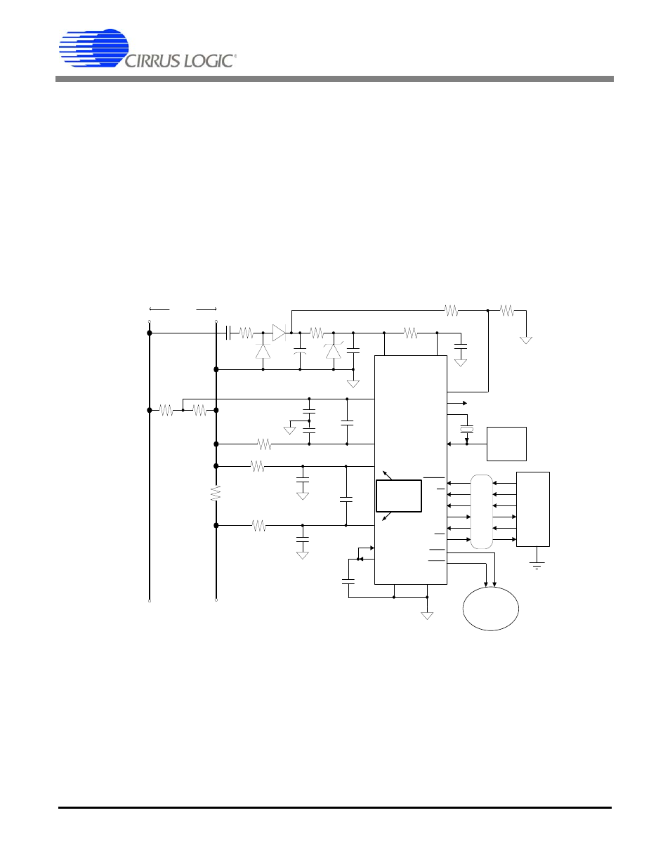
complete isolation from the power lines. This isola-
tion is achieved using three transformers. One
transformer is a general-purpose voltage trans-
former, used to supply the on-board DC power to
the CS5460A. A second transformer is a high-pre-
cision, low-impedance voltage transformer (often
called a ‘potential transformer’) with very little
roll-off/phase delay, even at the higher harmonics.
A current transformer is then used to sense the line
current. A burden resistor placed across the sec-
ondary of the current transformer creates the cur-
rent-sense voltage signal, for the CS5460A’s
current channel inputs. Because the CS5460A is
not directly connected to the power mains, isola-
tion is not required for the CS5460A’s digital inter-
face.
Figure 8 shows the CS5460A configured to mea-
sure power in a single-phase 3-wire system. In
many 3-wire residential power systems within the
United States, only the two Line terminals are
available (neutral is not available). Figure 9 shows
how the CS5460A can be configured to meter a
3-wire system when no neutral is available.
VA+
VD+
0.1 µF
100 µF
500
470 nF
500
N
R
1
R
2
10
14
VIN+
9
VIN-
IIN-
10
15
16
IIN+
PFMON
CPUCLK
XOUT
XIN
Optional
Clock
Source
Serial
Data
Interface
RESET
17
2
1
24
19
CS
7
SDI
23
SDO
6
SCLK
5
INT
20
EDIR
EOUT
0.1 µF
VREFIN
12
VREFOUT
11
VA-
DGND
13
4
3
To Service
2.5 MHz to
20 MHz
0.1 µF
C
10 k
5 k
L
R
Shunt
V+
*
* Refer to Input Protection
CS5460A
*
** Refer to Input Filtering
R
V-
*
R
I-
*
R
I+
*
C
I+
* *
ISOLATION
120 VAC
Mech. Counter
Stepper Motor
or
22
21
+
NOTE: Current channel
input measures voltage
(just like voltage input).
C
V-
* *
C
I-
* *
C* *
Vdiff
C* *
Idiff
Figure 6. Typical Connection Diagram (One-Phase 2-Wire, Direct Connect to Power Line)