4 analog connections, Figure 24. cs5351 recommended analog input buffer, 5 high-pass filter and dc offset calibration – Cirrus Logic CS5351 User Manual
Page 18: Cs5351
18
DS565F2
CS5351
4.4
Analog Connections
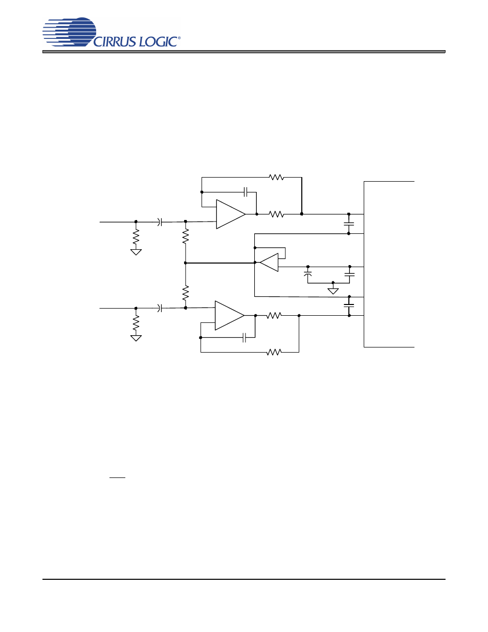
The analog modulator samples the input at 6.144 MHz. The digital filter will reject signals within the stop-
band of the filter. However, there is no rejection for input signals which are (n
×
6.144 MHz) the digital pass-
band frequency, where n=0,1,2,...Refer to
which shows the suggested filter that will attenuate any
noise energy at 6.144 MHz, in addition to providing the optimum source impedance for the modulators. The
use of capacitors which have a large voltage coefficient (such as general purpose ceramics) must be avoid-
ed since these can degrade signal linearity.
4.5
High-Pass Filter and DC Offset Calibration
The operational amplifiers in the input circuitry driving the CS5351 may generate a small DC offset into the
A/D converter. The CS5351 includes a high pass filter after the decimator to remove any DC offset which
could result in recording a DC level, possibly yielding "clicks" when switching between devices in a multi-
channel system.
The high pass filter continuously subtracts a measure of the DC offset from the output of the decimation
filter. If the HPF pin is taken high during normal operation, the current value of the DC offset register is frozen
and this DC offset will continue to be subtracted from the conversion result. This feature makes it possible
to perform a system DC offset calibration by:
Running the CS5351 with the high pass filter enabled until the filter settles. See the Digital Filter Character-
istics for filter settling time.
Disabling the high pass filter and freezing the stored DC offset.
A system calibration performed in this way will eliminate offsets anywhere in the signal path between the
calibration point and the CS5351.
Figure 24. CS5351 Recommended Analog Input Buffer
AINL
VQ1
VQ3
-
+
470 pF
C0G
CS5351
634
Ω
91
Ω
2700 pF
C0G
1
μF
1
μF
100 k
Ω
100 k
Ω
1
μF
0.01
μF
AINR
2700 pF
C0G
-
+
470 pF
C0G
91
Ω
634
Ω
-
+
VQ2
100 k
Ω
100 k
Ω