3 power supply droop test, An257 – Cirrus Logic AN257 User Manual
Page 6
AN257
6
AN257REV1
2.3
Power Supply Droop Test
To demonstration how PSR Feedback can compensate for droop in the power supply rail, per-
form the following using the CDB44800:
1) Using the setup from above, with PSR calibrated and enabled, and Vpower set to +40 V, playback a
1-kHz tone with an amplitude of approximately 10 V peak-to-peak (or any amplitude desired). Use one
channel of an oscilloscope to monitor the sine wave output of channel A. Use another channel of the
oscilloscope to monitor the DC voltage on Vpower.
2) Vary Vpower down to +30 V. Even though the Vpower supply will drop to +30 V from +40 V, the peak-
to-peak level of the sine wave output from channel A will remain constant.
This test shows how PSR Feedback will maintain the amplified audio level even if the power sup-
ply drops in voltage (common when low-frequency audio is played). The maximum amount of
voltage rail droop compensation is limited to 10% of the nominal rail when playing back a full-
scale signal. As the signal being played back is reduced in amplitude, more droop in the voltage
rail can be compensated.
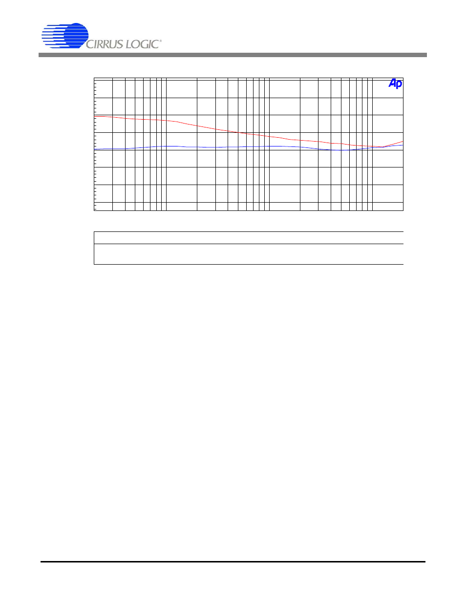
Color
Sweep
Trace
Line Style
Thick
Data
Axis
Comment
1
1
Red
Solid
1
Anlr.Ampl
Left
PSR feedback disabled
2
1
Blue
Solid
1
Anlr.Ampl
Left
PSR feedback enabled
-140
+0
-120
-100
-80
-60
-40
-20
d
B
r
A
20
20k
50
100
200
500
1k
2k
5k
10k
Hz
Figure 6. PSR Disabled vs. PSR Enabled
Channel A = “on”, but muted (zero data), sweep Channel B frequency @ 0 dBFS