An257 – Cirrus Logic AN257 User Manual
Page 3
AN257
AN257REV1
3
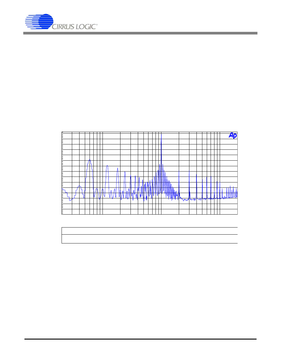
5) Turn on the channel B PWM output and take an FFT of amplitude versus frequency for channel A. The
1-kHz tone should be present with an amplitude of
-
1 dBFS (with modulated side tones) along with a
60-Hz tone and associated harmonics. Figure 2 shows the FFT of channel A with both channel A and
channel B PWM outputs enabled. The original 1-kHz tone is shown at
-
1-dBFS, with the coupled 60-
Hz tone from channel B shown at
-
50 dBFS. The full scale, 60 Hz tone being played back on
channel B’s MOSFET devices causes an associated 60-Hz ripple current on the power voltage rail.
This ripple current, along with the capacitor’s equivalent series resistance (ESR), causes the discrete
tones on the power supply rail. Notice the 2nd, 3rd, 4th, 5th, etc. harmonics at 120 Hz, 180 Hz,
240 Hz, 300 Hz, etc. due to the system non-linearities. Because all of these tones are being modulat-
ed onto channel A’s audio output by the power MOSFETs switching at a 384-kHz rate, these discrete
tones will also be modulated onto the 1-kHz tone being played back (see tones grouped around
1 kHz). These modulated tones appear as symmetrical, equidistant tones on each side of the 1-kHz
tone. The amplitude and frequency of each modulated tone is easily calculated using standard FM
modulation formulas.
6) Enable PSR Feedback (CS44800/44600 bit 5 in register 34h set to 1b). Take an FFT of amplitude ver-
sus frequency on the output of channel A. The 1-kHz tone should be present with an amplitude of
-
1 dBFS, however the 60-Hz tone and the modulated side tones will be greatly diminished in ampli-
tude. Figure 3 shows the results of having both channels on and PSR feedback enabled.
Color
Sweep
Trace
Line Style
Thick
Data
Axis
Comment
2
1
Blue
Solid
-1
Fft.Ch.1 Ampl
Left
Channel B = 60 Hz, 0 dBFS, PSR feedback disabled
-150
+0
-140
-130
-120
-110
-100
-90
-80
-70
-60
-50
-40
-30
-20
-10
d
B
r
A
20
20k
50
100
200
500
1k
2k
5k
10k
Hz
Figure 2. FFT Amplitude vs. Frequency,
Channel A = 1 kHz,
-
1 dBFS, Channel B = 60 Hz, 0 dBFS, PSR feedback disabled