Figure 14. format 5 - right-justified 18-bit data, 1 olm #1, Figure 15. format 8 - one line mode 1 – Cirrus Logic CS4384 User Manual
Page 23: 2 olm #2, Figure 16. format 9 - one line mode 2, 1 olm #1 4.3.2 olm #2, Cs4384
DS620F1
23
CS4384
4.3.1
OLM #1
OLM #1 serial audio interface format operates in Single-, Double-, or Quad-Speed Mode and will slave to
SCLK at 128 Fs. Six channels of MSB first 20-bit PCM data are input on SDIN1. The last two channels
are input on SDIN4.
4.3.2
OLM #2
OLM #2 serial audio interface format operates in Single-, Double-, or Quad-Speed Mode and will slave to
SCLK at 256 Fs. Six channels of MSB first 24-bit PCM data are input on SDIN1. The last two channels
are input on SDIN4.
LRCK
SCLK
Left Channel
Right Channel
SDINx
6
5
4
3
2
1
0
9
8
7
15 14 13 12 11 10
1
0
6
5
4
3
2
1
0
9
8
7
15 14 13 12 11 10
17 16
17 16
32 clocks
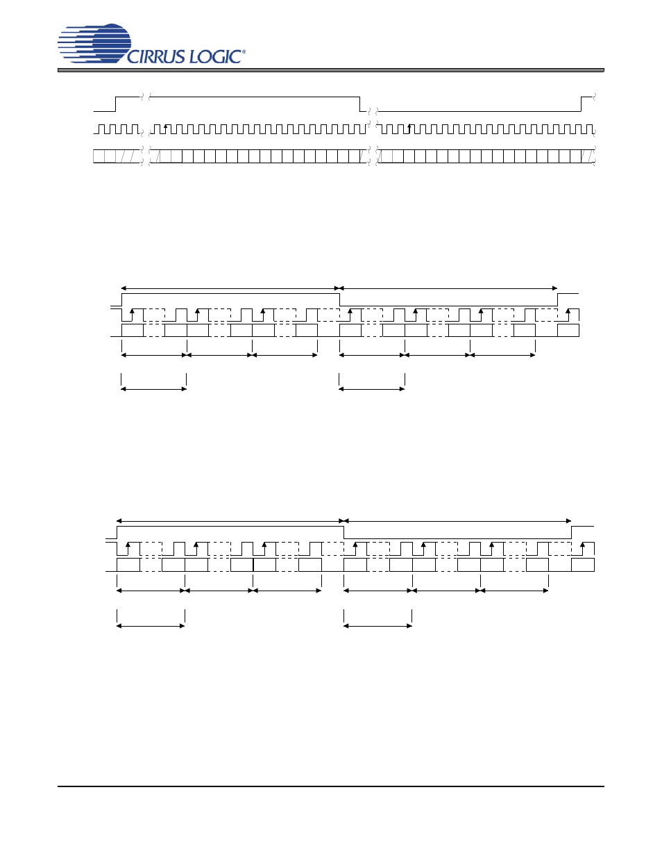
Figure 14. Format 5 - Right-Justified 18-bit Data
LRCK
SCLK
LSB
MSB
20 clks
64 clks
64 clks
LSB
MSB
LSB
MSB
LSB
MSB
LSB
MSB
LSB
MSB
MSB
DAC_A1
20 clks
20 clks
20 clks
20 clks
20 clks
Left Channel
Right Channel
20 clks
20 clks
SDIN4
SDIN1
DAC_A2
DAC_A3
DAC_A4
DAC_B1
DAC_B4
DAC_B2
DAC_B3
Figure 15. Format 8 - One Line Mode 1
LSB
MSB
24 clks
128 clks
LSB
MSB
LSB
MSB
LSB
MSB
LSB
MSB
LSB
MSB
MSB
DAC_A1
24 clks
24 clks
24 clks
24 clks
24 clks
Left Channel
Right Channel
24 clks
24 clks
128 clks
LRCK
SCLK
SDIN1
SDIN4
DAC_A4
DAC_A2
DAC_A3
DAC_B1
DAC_B2
DAC_B3
DAC_B4
Figure 16. Format 9 - One Line Mode 2