Applications, 1 master clock, 2 mode select – Cirrus Logic CS4362A User Manual
Page 21: 1 master clock 4.2 mode select, Table 1. common clock frequencies
DS617F2
21
CS4362A
4. APPLICATIONS
The CS4362A serially accepts two’s-complement formatted PCM data at standard audio sample rates including 48,
44.1, and 32 kHz in SSM, 96, 88.2, and 64 kHz in DSM, and 192, 176.4, and 128 kHz in QSM. Audio data is input
via the serial data input pins (SDINx). The Left/Right Clock (LRCK) determines which channel is currently being input
on SDINx, and the Serial Clock (SCLK) clocks audio data into the input data buffer.
The CS4362A can be configured in Hardware Mode by the M0, M1, M2, M3, and DSD_EN pins and in Software
Mode through I²C or SPI.
4.1
Master Clock
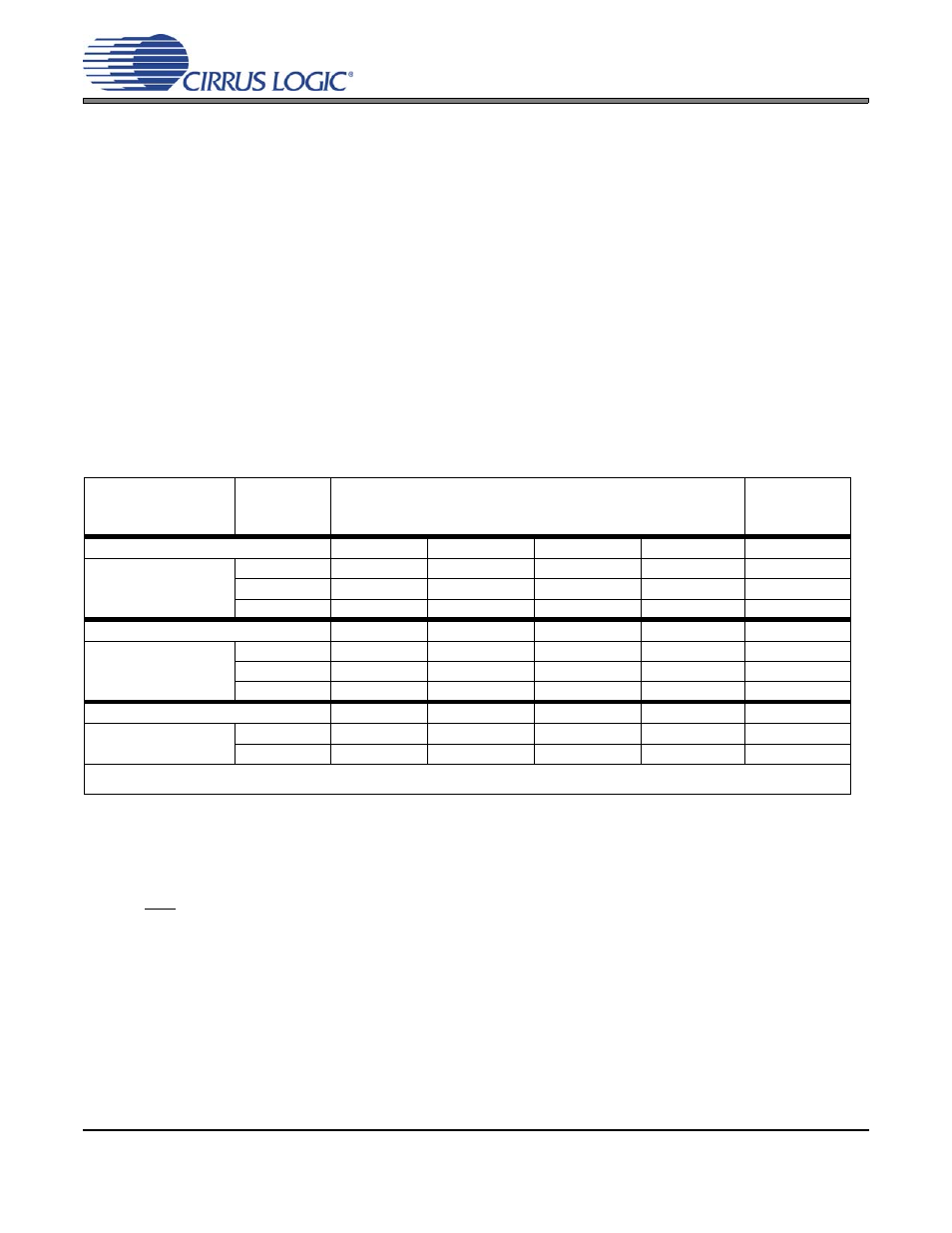
MCLK/LRCK must be an integer ratio as shown in
. The LRCK frequency is equal to Fs, the frequen-
cy at which words for each channel are input to the device. The MCLK-to-LRCK frequency ratio is detected
automatically during the initialization sequence by counting the number of MCLK transitions during a single
LRCK period. Internal dividers are then set to generate the proper internal clocks.
illustrates several
standard audio sample rates and the required MCLK and LRCK frequencies. Please note there is no re-
quired phase relationship, but MCLK, LRCK, and SCLK must be synchronous.
4.2
Mode Select
In Hardware Mode, operation is determined by the Mode Select pins. The states of these pins are continu-
ally scanned for any changes; however, the mode should only be changed while the device is in reset
(RST pin low) to ensure proper switching from one mode to another. These pins require connection to sup-
ply or ground as outlined in
. VLC supplies M0, M1, and M2. VLS supplies M3 and DSD_EN.
show the decode of these pins.
In Software Mode, the operational mode and data format are set in the FM and DIF registers. See
Interface Format (DIF)” on page 34
“Functional Mode (FM)” on page 40
.
Speed Mode
(sample-rate range)
Sample
Rate
(kHz)
MCLK (MHz)
Software
Mode Only
MCLK Ratio
256x
384x
512x
768x
1024x*
Single-Speed
(4 to 50 kHz)
32
8.1920
12.2880
16.3840
24.5760
32.7680
44.1
11.2896
16.9344
22.5792
33.8688
45.1584
48
12.2880
18.4320
24.5760
36.8640
49.1520
MCLK Ratio
128x
192x
256x
384x
512x*
Double-Speed
(50 to 100 kHz)
64
8.1920
12.2880
16.3840
24.5760
32.7680
88.2
11.2896
16.9344
22.5792
33.8688
45.1584
96
12.2880
18.4320
24.5760
36.8640
49.1520
MCLK Ratio
64x
96x
128x
192x
256x*
Quad-Speed
(100 to 200 kHz)
176.4
11.2896
16.9344
22.5792
33.8688
45.1584
192
12.2880
18.4320
24.5760
36.8640
49.1520
Note:
These modes are only available in Software Mode by setting the MCLKDIV bit = 1.
Table 1. Common Clock Frequencies