Cirrus Logic CS4339 User Manual
Pin, 24-bit, 96 khz stereo d/a converter, Features, Description
Copyright
Cirrus Logic, Inc. 2012
(All Rights Reserved)
8-Pin, 24-Bit, 96 kHz Stereo D/A Converter
Features
Complete Stereo DAC System: Interpolation,
D/A, Output Analog Filtering
24-Bit Conversion
96 dB Dynamic Range
-88 dB THD+N
Low Clock-Jitter Sensitivity
Single +5 V Power Supply
Filtered Line-Level Outputs
On-Chip Digital De-emphasis
Popguard
®
Technology
Functionally Compatible with CS4330/31/33
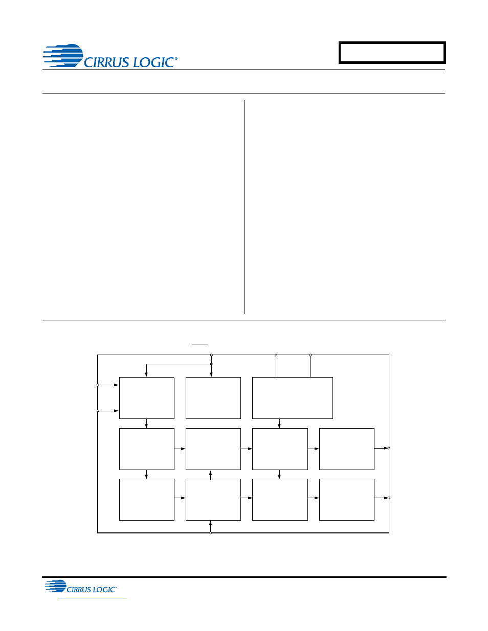
Description
The CS4334 family members are complete, stereo dig-
ital-to-analog output systems including interpolation,
1-bit D/A conversion and output analog filtering in an
8-pin package. The CS4334/5/8/9 support all major au-
dio data interface formats, and the individual devices
differ only in the supported interface format.
The CS4334 family is based on Delta-Sigma modula-
tion, where the modulator output controls the reference
voltage input to an ultra-linear analog low-pass filter.
This architecture allows for infinite adjustment of sam-
ple rate between 2 kHz and 100 kHz simply by
changing the master clock frequency.
The CS4334 family contains on-chip digital de-empha-
sis, operates from a single +5V power supply, and
requires minimal support circuitry. These features are
ideal for set-top boxes, DVD players, SVCD players,
and A/V receivers.
ORDERING INFORMATION
See
“Ordering Information” on page 24
LRCK
3
SDATA
1
DEM/SCLK
2
MCLK
4
VA
AOUTL
8
AOUTR
5
Serial Input
Interface
Interpolator
Interpolator
De-emphasis
Modulator
Modulator
DAC
DAC
Voltage Reference
Analog
Low-Pass
Filter
Analog
Low-Pass
Filter
7
AGND
6
JANUARY '12
DS248F6
Confidential Draft
1/18/12
CS4334/5/8/9
Document Outline
- 1. Typical Connection Diagram
- 2. Characteristics and Specifications
- 3. General Description
- 4. System Design
- 4.1 Master Clock
- 4.2 Serial Clock
- 4.3 De-Emphasis
- 4.4 Initialization and Power-Down
- 4.5 Output Transient Control
- 4.6 Grounding and Power Supply Decoupling
- 4.7 Analog Output and Filtering
- 4.8 Overall Base-Rate Frequency Response
- 4.9 Overall High-Rate Frequency Response
- 4.10 Base Rate Mode Performance Plots
- 4.11 High Rate Mode Performance Plots
- 5. Parameter Definitions
- 6. References
- 7. Package Dimensions
- 8. Ordering Information
- 9. Functional Compatibility
- 10. Revision History