2 serial control within a multiple-cs3308 system, Figure 9. spi serial control connections, 1 spi mode serial control configuration – Cirrus Logic CS3308 User Manual
Page 24: Figure 9.spi serial control connections, Section 5.8.2 on, Cs3308
24
DS702F1
CS3308
5.8.2
Serial Control within a Multiple-CS3308 System
The CS3308 allows both independent and simultaneous control of up to 128 devices on a shared I²C or
SPI serial control bus. The address of each device is configured by the host controller via the shared serial
control bus. All serial communication, including the configuration of each device’s address, adheres to a
standard I²C or SPI bus protocol.
A device’s Individual device address, which provides read and write access to the device’s internal regis-
ters, should be set to a unique value, different from all other addresses recognized by devices on the serial
communication bus. This address facilitates independent control of each CS3308 on the serial control
bus.
A device’s Group 1 and Group 2 addresses, which provide write-only access to the device’s internal reg-
isters, may be set to the same value across multiple CS3308’s on the shared serial communication bus.
Assigning common Group addresses to multiple devices in a system allows system sub-master and sys-
tem master volume control. For instance, a system containing 8 CS3308’s may configure the Group 1 ad-
dress of the first set of 4 CS3308’s to 10h, the Group 1 address of the second set of 4 CS3308’s to 20h,
and the Group 2 address of all 8 CS3308’s to A0h. In this manner, a serial control data write to address
10h would act as a system sub-master control to the first set of 4 devices, a write to 20h would act as a
system sub-master control to the second set of 4 devices, and a write to A0h would act as a system mas-
ter control to all devices.
By default, the CS3308 will not respond to serial communication when addressed with its Group 1 or
Group 2 address. The CS3308 will only respond to one or both of these addresses if the corresponding
address has been enabled via the control port. To enable a Group address, its corresponding Enable bit,
located in the LSB of its respective Group address register, must be set.
The CS3308 implements an ENOut signal to facilitate the device address configuration process. This sig-
nal is used to hold all but one un-configured device in a reset state. After the Individual device address of
each device has been set, the ENOut signal is used to enable the “next” device in the chain, allowing its
Individual device address to be set. See
“SPI Mode Serial Control Configuration” section on page 24
and
“I²C Mode Control Configuration” on page 26
for more information about system configuration in each
communication mode.
5.8.2.1
SPI Mode Serial Control Configuration
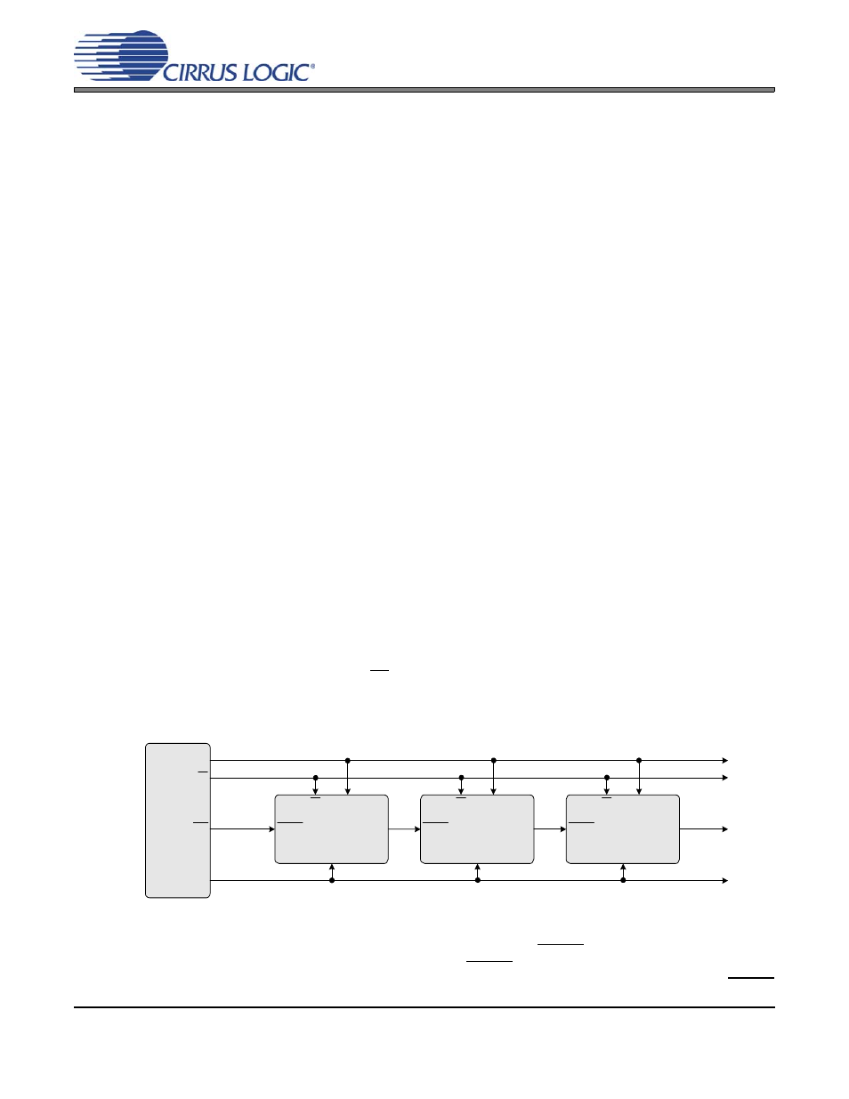
Up to 128 CS3308’s sharing the same CS signal may be connected to a common SPI serial control bus.
This shared serial bus is used to assign a unique device address to each device on the bus such that they
may be independently addressed. To implement this method of device address configuration, the devices
must be connected as shown in
Note that the serial control signals CCLK, CS, and MOSI are connected in parallel to each CS3308. The
active low reset output of the system controller is connected to the RESET input of the first CS3308 in the
chain. The ENOut of the first device is connected to the RESET input of the second CS3308 whose ENOut
signal is connected to the third CS3308. This pattern of connecting the ENOut of device N to the RESET
μC
CCLK
MOSI
CS
Device 1
CS
CCLK
MOSI
RESET
ENout
Device 2
CS
CCLK
MOSI
RESET
ENout
Device 3
CS
CCLK
MOSI
RESET
ENout
RST
Figure 9. SPI Serial Control Connections