2 volume & muting control implementation, Figure 6. volume & muting control implementation, Figure 6.volume & muting control implementation – Cirrus Logic CS3308 User Manual
Page 18: Volume & muting control implementation” section on, Cs3308
18
DS702F1
CS3308
Combining the multiple group addressing capabilities of the CS3308 (as detailed in
) with the internal master control mapping abilities described above allows the configuration and
direct addressing of multiple logical groups of channels across multiple CS3308 devices within a system.
5.4.2
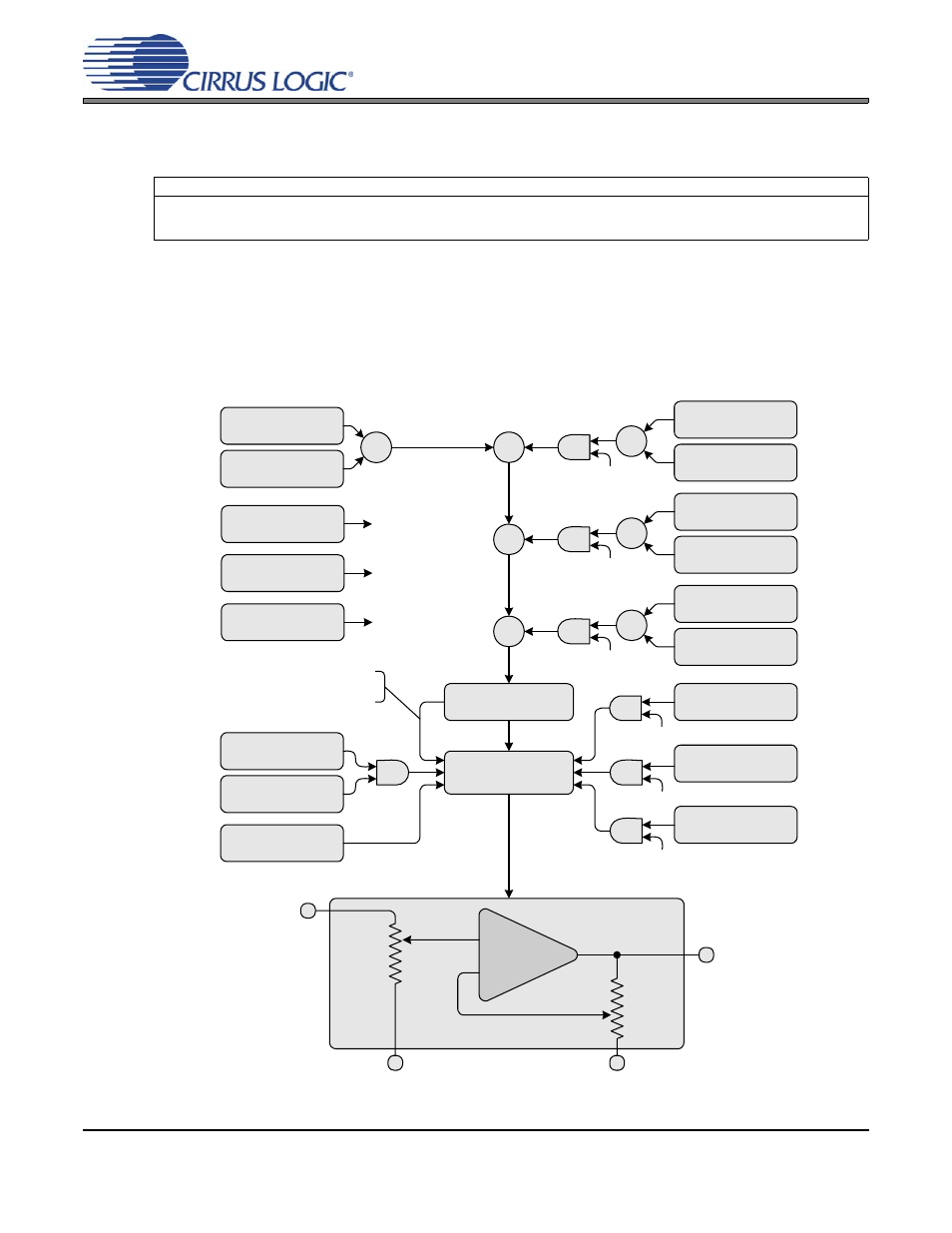
Volume & Muting Control Implementation
below diagrams in detail the volume and muting control architecture of the CS3308 for an arbi-
trary channel ‘N’.
This diagram incorporates all volume and muting control concepts presented in sections
included as a reference and will serve to corroborate the information presented in these sections.
Referenced Control
Register Location
Master X Mask ....................
“Master 1 Mask - Address 10h” on page 36
“Master 2 Mask - Address 13h” on page 37
“Master 3 Mask - Address 16h” on page 38
Limit Volume Result
-96 dB to +22 dB
Ch. N - Volume
Register N
Ch. N - ¼ dB Control
Register 09h, Bit N-1
Σ
Ch. N Master 2 Mask
Register 13h, Bit N-1
Hardware Mute Input
Pin 4
Master 1 - Mute
Register 12h, Bit 1
Mute
Channel N - Mute
Register 0Ah, Bit N-1
Master 3 - Mute
Register 18h, Bit 1
Master 2 - Mute
Register 15h, Bit 1
Ch. N Master 1 Mask
Register 10h, Bit N-1
Ch. N Master 3 Mask
Register 16h, Bit N-1
_
+
Channel N
REFI
REFO
Input
Output
Σ
Mask 1
Mask 2
Mask 3
Master 1 - Volume
Register 11h
Master 1 - ¼ dB
Register 12h, Bit 0
Σ
Master 2 - Volume
Register 14h
Master 2 - ¼ dB
Register 15h, Bit 0
Σ
Mask 2
Master 3 - Volume
Register 17h
Master 3 - ¼ dB
Register 18h, Bit 0
Σ
Mask 3
Mask 1
Mask 1
Mask 3
Σ
Σ
Mask 2
Mute Input Enable
Register 0Bh, Bit 5
Mute if result is
less than -96 dB.
Figure 6. Volume & Muting Control Implementation