3 differential signals, 4 guard output, 2 digital signals – Cirrus Logic CS3302A User Manual
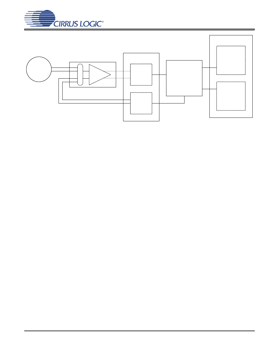
Page 11: 1 gain selection, Differential signals 2.5.4.guard output, Digital signals, Gain selection, Figure 4. system architecture, Cs3302a
CS3302A
CS3302A
DS765PP1
DS765PP1
11
requires two series resistors and a differential capaci-
tor to create the modulator anti-alias RC filter.
2.1.3
Differential Signals
Analog signals into and out of the CS3302A are
differential, consisting of two halves with equal but
opposite magnitude varying about a common mode
voltage.
A full scale 5 V
pp
differential signal centered on a
-0.15 V common mode can have:
SIG+ = -0.15 V + 1.25 V = 1.1 V
SIG- = -0.15 V - 1.25 V = -1.4 V
SIG+ is +2.5 V relative to SIG-
For the reverse case:
SIG+ = -0.15 V - 1.25 V = -1.4 V
SIG- = -0.15 V + 1.25 V = 1.1 V
SIG+ is -2.5 V relative to SIG-
The total swing for SIG+ relative to SIG- is
(+2.5 V) - (-2.5 V) = 5 V
pp
. A similar calculation
can be done for SIG- relative to SIG+. Note that a
5 V
pp
differential signal centered on a -0.15 V
common mode voltage never exceeds 1.1 V and
never drops below -1.4 V on either half of the sig-
nal.
By definition, differential voltages are to be mea-
sured with respect to the opposite half, not relative
to ground. A multimeter differentially measuring
between SIG+ and SIG- in the above example
would properly read 1.767 V
rms
, or 5 V
pp
.
2.1.4
Guard Output
The GUARD pin outputs the common mode volt-
age of the currently selected analog signal input. It
can be used to drive the cable shield between a
high-impedance sensor and the amplifier inputs.
Driving the cable shield with the analog signal
common mode voltage minimizes leakage and im-
proves signal integrity from high-impedance sen-
sors.
The GUARD output is defined as the midpoint
voltage between the + and - halves of the currently
selected differential input signal, and will vary as
the signal common mode varies. The GUARD out-
put will not drive a significant load, it only pro-
vides a shielding voltage.
2.2
Digital Signals
2.2.1
Gain Selection
The CS3302A supports gain ranges of x1, x2, x4,
x8, x16, x32, and x64. They are selected using the
GAIN0, GAIN1, and GAIN2 pins as shown in
∆Σ
Modulator
Test
DAC
Digital Filter
AMP
Differential
Sensor
M
U
X
µController
or
Configuration
EEPROM
System
Telemetry
CS3301A
CS3302A
CS5378
CS5373A
Figure 4. System Architecture