7 function configuration 2 (address 17h), 1 enable pll clock output on unlock (clkoutunl), 2 low-frequency ratio configuration (lfratiocfg) – Cirrus Logic CS2300-CP User Manual
Page 28: 8 function configuration 3 (address 1eh), 1 clock input bandwidth (clkin_bw[2:0]), P 28, Cs2300-cp
CS2300-CP
28
DS843F2
8.7
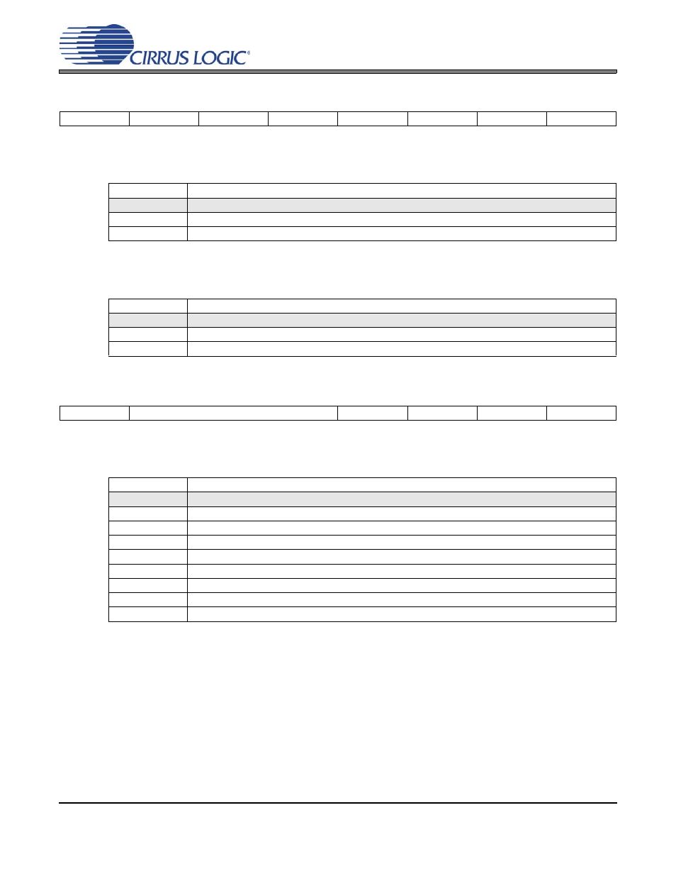
Function Configuration 2 (Address 17h)
8.7.1
Enable PLL Clock Output on Unlock (ClkOutUnl)
Defines the state of the PLL output during the PLL unlock condition.
8.7.2
Low-Frequency Ratio Configuration (LFRatioCfg)
Determines how to interpret the 32-bit User Defined Ratio.
8.8
Function Configuration 3 (Address 1Eh)
8.8.1
Clock Input Bandwidth (ClkIn_BW[2:0])
Sets the minimum loop bandwidth when locked to CLK_IN.
Note:
In order to guarantee that a change in minimum bandwidth takes effect, these bits must be set
prior to acquiring lock (removing and re-applying CLK_IN can provide the unlock condition necessary to
initiate the setting change). In production systems these bits should be configured with the desired values
prior to setting the EnDevCfg bits; this guarantees that the setting takes effect prior to acquiring lock.
7
6
5
4
3
2
1
0
Reserved
Reserved
Reserved
ClkOutUnl
LFRatioCfg
Reserved
Reserved
Reserved
ClkOutUnl
Clock Output Enable Status
0
Clock outputs are driven ‘low’ when PLL is unlocked.
1
Clock outputs are always enabled (results in unpredictable output when PLL is unlocked).
Application:
LFRatioCfg
Ratio Bit Encoding Interpretation
0
20.12 - High Multiplier.
1
12.20 - High Accuracy.
Application:
“User Defined Ratio (RUD)” on page 16
7
6
5
4
3
2
1
0
Reserved
ClkIn_BW2
ClkIn_BW1
ClkIn_BW0
Reserved
Reserved
Reserved
Reserved
ClkIn_BW[2:0]
Minimum Loop Bandwidth
000
1 Hz
001
2 Hz
010
4 Hz
011
8 Hz
100
16 Hz
101
32 Hz
110
64 Hz
111
128 Hz
Application:
“Adjusting the Minimum Loop Bandwidth for CLK_IN” on page 15