3 pll clock output disable (clkoutdis), 3 device configuration 1 (address 03h), 1 r-mod selection (rmodsel[2:0]) – Cirrus Logic CS2000-CP User Manual
Page 29: 2 ratio selection (rsel[1:0]), P 29, Cs2000-cp
CS2000-CP
DS761F2
29
8.2.3
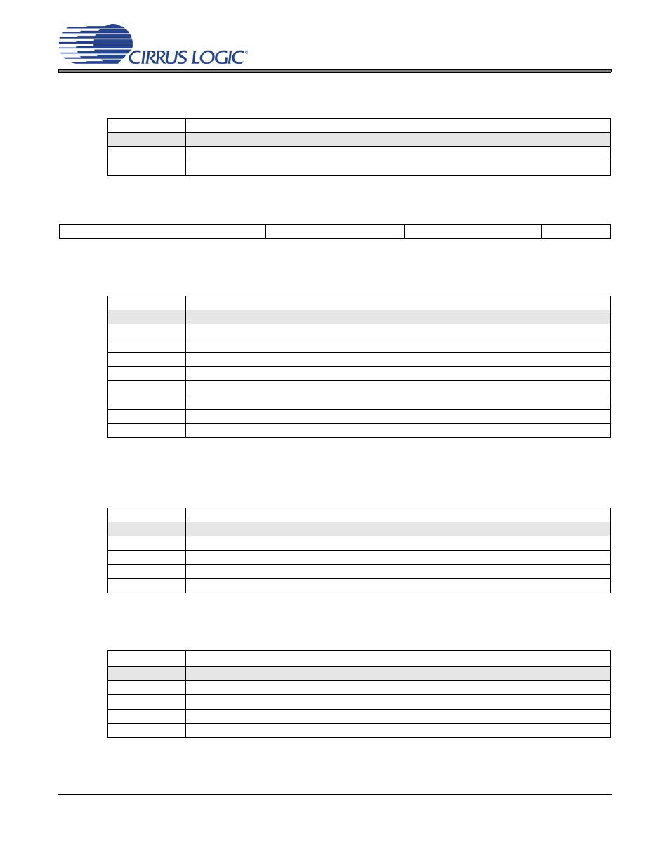
PLL Clock Output Disable (ClkOutDis)
This bit controls the output driver for the CLK_OUT pin.
8.3
Device Configuration 1 (Address 03h)
8.3.1
R-Mod Selection (RModSel[2:0])
Selects the R-Mod value, which is used as a factor in determining the PLL’s Fractional N.
8.3.2
Ratio Selection (RSel[1:0])
Selects one of the four stored User Defined Ratios for use in the static ratio based Frequency Synthesizer
Mode.
8.3.3
Auxiliary Output Source Selection (AuxOutSrc[1:0])
Selects the source of the AUX_OUT signal.
Note:
When set to 11, AuxLckCfg sets the polarity and driver type. See
uration (AuxLockCfg)” on page 32
ClkOutDis
Output Driver State
0
CLK_OUT output driver enabled.
1
CLK_OUT output driver set to high-impedance.
Application:
7
6
5
4
3
2
1
0
RModSel2
RModSel1
RModSel0
RSel1
RSel0
AuxOutSrc1
AuxOutSrc0
EnDevCfg1
RModSel[2:0]
R-Mod Selection
000
Left-shift R-value by 0 (x 1).
001
Left-shift R-value by 1 (x 2).
010
Left-shift R-value by 2 (x 4).
011
Left-shift R-value by 3 (x 8).
100
Right-shift R-value by 1 (÷ 2).
101
Right-shift R-value by 2 (÷ 4).
110
Right-shift R-value by 3 (÷ 8).
111
Right-shift R-value by 4 (÷ 16).
Application:
“Ratio Modifier (R-Mod)” on page 20
RSel[1:0]
Ratio Selection
00
Ratio 0.
01
Ratio 1.
10
Ratio 2.
11
Ratio 3.
Application:
“User Defined Ratio (RUD), Frequency Synthesizer Mode” on page 19
AuxOutSrc[1:0]
Auxiliary Output Source
00
RefClk.
01
CLK_IN.
10
CLK_OUT.
11
PLL Lock Status Indicator.
Application: