1 cobranet clock modes, 1 0x00 mode - internal mode (default), Figure 3. 0x00 mode typical connections – Cirrus Logic AN312 User Manual
Page 3: An312
AN312REV2
3
AN312
3.1
CobraNet Clock Modes
This section describes each of the CobraNet clock modes.
3.1.1
0x00 Mode - Internal Mode (Default)
The 0x00 Mode is the default clock mode of a CobraNet interface. When operating in this mode:
•
As Conductor: The master audio clock (MCLK) is generated by the VXCO parked at its center fre-
quency. Word clock (FS1) and bit clock (SCLK) are derived directly from MCLK.
•
As Performer: The master audio clock (MCLK) is generated by the VXCO, which receives frequency
adjustments from the beat packets received from the Conductor node over the network interface, in-
suring that the Performer's clock is in sync with the Conductor. Word clock (FS1) and bit clock (SCLK)
are derived from MCLK.
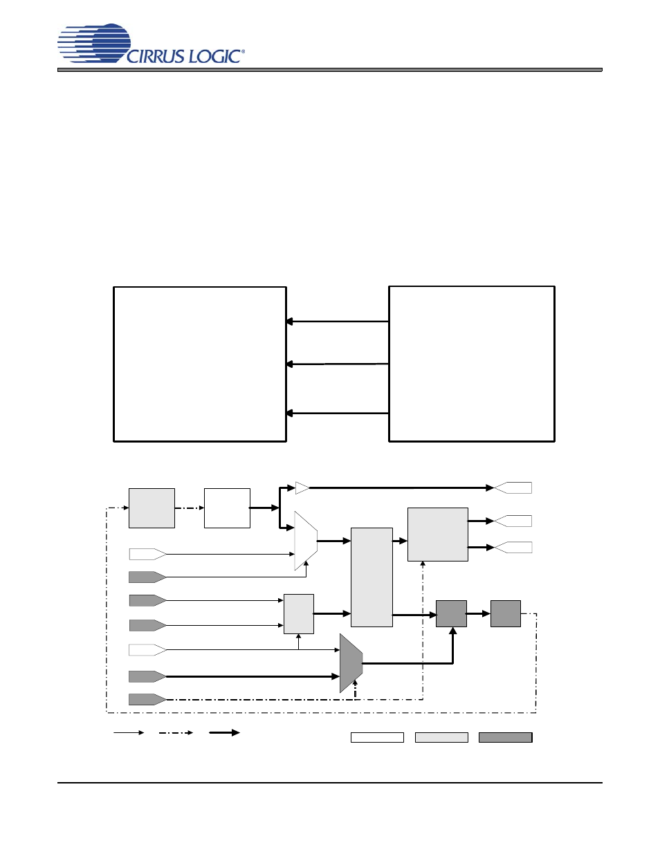
Figure 3. 0x00 Mode Typical Connections
Figure 4. Clock Circuit as Used by 0x00 Mode with CM-1 Module
CobraNet Interface
FS1
(LR clock)
SCLK
(Bit clock)
MCLK_OUT
(Master Audio
Clock)
DAC or ADC
Beat R eceived
V C XO
24.576 M H z
+/- 100 P PM
D AC
M C LK_IN
M C LK_SEL
R EFC LK_Enable
R EFC LK _Polarity
R EF C LK
Edge
D etect
M C LK
M U X
Beat
M U X
P hase
D etector
Sam ple
Phase
C ounter
R ST
Loop
Filter
control
C lock
O ut
M C LK_O U T (m aster)
FS1 (w ord)
SC K (bit)
Audio
C lock
G enerator
C lock C onfig
Signal
Path
C ontrol
Path
H ardw are
FP G A
Softw are
Active
Signal
Path