2 definition of symbols, An375 – Cirrus Logic AN375 User Manual
Page 4
AN375
4
AN375REV4
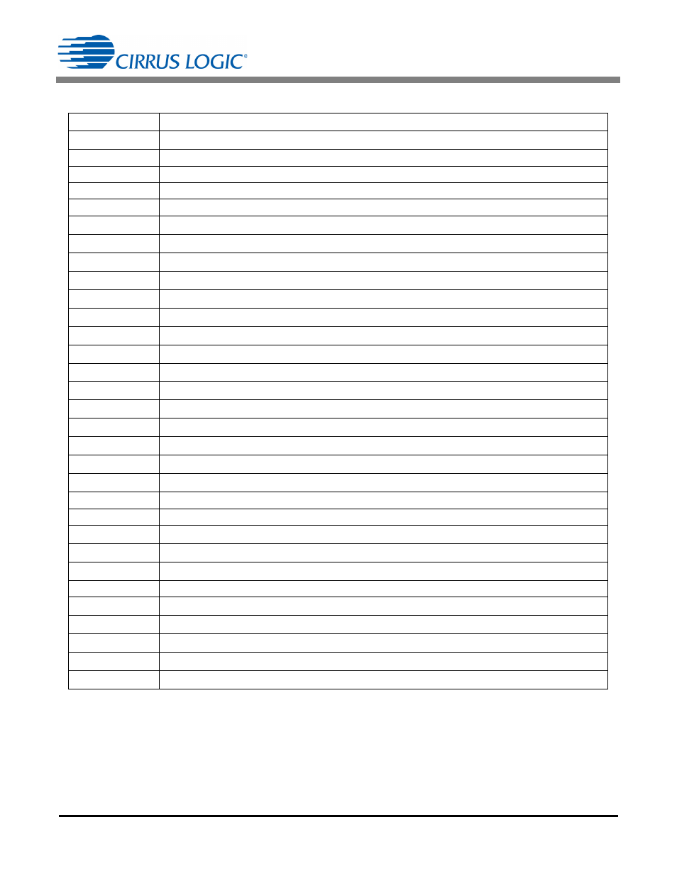
2.2 Definition of Symbols
Symbol
Description
F
SW
Switching frequency
TT
Switching period
T1
Primary FET ‘ON’ time
T2
Secondary rectifier diode conduction time
T3
Time when the FET and diode are ‘OFF’
V
Reflected
Voltage across secondary winding reflected onto primary during T2
V
Zener
Primary clamping voltage above flyback input voltage
I
PK
Peak current in primary-side FET
R
CTRL1
Resistor used to set the minimum input current being pulled by the flyback
R
Sense
Primary current sense resistor
R
CTRL2
Resistor used to set the output current through the LED string
R
NTC
Negative temperature coefficient resistance
L
P
Flyback transformer primary inductance
I
hold
TRIAC holding current
N
Flyback transformer turns ratio N
P
/N
S
V
OUT
Secondary output DC voltage and the LED string supply voltage
V
IN
AC RMS line voltage
P
OUT
Load power = Power to the LED string
I
OUT
Nominal LED string DC current
P
IN
Input power
Power stage efficiency
Duty ratio (T1/TT)
I
fb
Dimmer current at full brightness. Line current required to guarantee I
OUT
under worst case conditions
I
P(RMS)
Primary RMS current
I
S(RMS)
Secondary RMS current
Duty correction
V
INPK
Peak line voltage
I
INPK
Peak line current
Z
Ratio V
IN
/V
Reflected
I
IN(CC)
Constant input current
V
rect
Primary input voltage