An375 – Cirrus Logic AN375 User Manual
Page 10
AN375
10
AN375REV4
Ideally, reflected voltage V
Reflected
should have nearly the same value as peak line voltage V
INPK
because
operating the transformer near 50% duty cycle optimizes the transformer efficiency. Alternatively, zener
voltage V
Zener
should be much greater than reflected voltage V
Reflected
to rapidly discharge the energy stored
in the transformer leakage inductance.
The FET breakdown voltage is constrained by cost and performance. A compromise must be reached in
partitioning voltage between voltages V
INPK
, V
Zener
, and V
Margin
. A second compromise will then determine
how to divide voltage V
Zener
into voltage V
Reflected
and a reasonable overshoot voltage portion, V
Overshoot
. The
losses caused by the leakage inductance are inversely proportional to voltage V
Overshoot
, which is determined
by Equation 7:
For optimum efficiency, the increase in transformer losses (created by an uneven duty cycle) must balance the
reduction of the losses caused by discharging the leakage inductance (obtained by increasing the overshoot
voltage). Balance all voltages that contribute to the drain and source voltages of the FET using Equation 8:
where
V
Overshoot
= voltage (V
Zener
- V
Reflected
)
The RC snubber is based on the principle that the time constant RC is much greater than switching period TT,
which assures the clamp voltage remains across the resistor for the entire switching period TT long after the
brief snubbing time has lapsed. This design approach assures that for high clamp voltages a large value
resistor can be used, since the resistor has the entire switching cycle available to dissipate the high peak
power P
leakage
present during the brief time required to extinguish the current in the leakage inductance.
The clamp voltage V
RC
across the RC snubber circuit changes with the varying peak current across the
different phases of the line voltage. Furthermore any variation of the leakage inductance, the switching
frequency, the drain node parasitic capacitance, or the FET turn ‘OFF’ time affects the energy flowing into the
RC snubber circuit changing the clamp voltage V
RC
.
The RC time constant must be much greater than the longest switching period TT allowing the RC circuit to
hold clamp voltage V
RC
constant across the switching period, but much shorter than the half-line period to
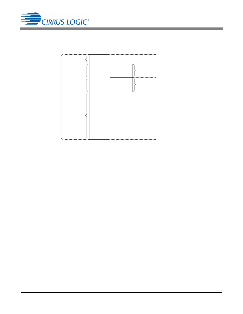
V
Margin
V
Zener
V
INPK
V
Overshoot
V
Reflected
FET Breakdown
Voltage Rating
Clamp
Zener
Voltage
Peak
Input
Voltage
Margin
Reflected
Voltage
Overshoot
Voltage
Overshoot is a brief condition above
reflected voltage V
Reflected
, required to
quickly dissipate the energy stored in
the transformer leakage inductance.
During this time, the primary current is
kept from transferring to the
secondary, siphoning energy from the
load to the zener clamp (snubber).
Figure 4. FET Breakdown Voltage
V
Overshoot
V
Zener
V
Reflected
–
=
[Eq. 7]
V
Breakdown
V
INPK
V
Reflected
V
Overshoot
+
V
M
in
arg
+
+
=
[Eq. 8]