An375 – Cirrus Logic AN375 User Manual
Page 12
AN375
12
AN375REV4
Step 6) Calculate Peak Current
The switching period TT used in Equation 13 on page 11 is found only at the peak of the minimum input line
voltage when reflected voltage V
Reflected
is at its minimum; this value coincides with a useful design point, but
it is not yet known whether this corresponds to a minimum or maximum switching frequency. Calculate peak
current I
PK
at minimum duty cycle
min
using Equation 14:
The peak current calculated in Equation 14 incorporates three margins to guarantee nominal load current:
• to the highest voltage load
• at the lowest line voltage
• with dimmer producing a conduction angle limited to 135°
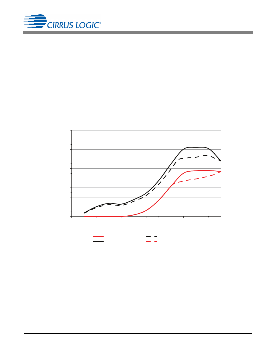
The graph in Figure 5 plots input and load power versus the dimmer conduction angle for a typical design.
As the dimmer cuts the conduction angle from 130° to 180°, the input power rises and stabilizes to a high value
while the load power stays constant. The excess power is dissipated in the dimmer compatibility block. The
excess power is proportionally larger for lower nominal power designs more likely to experience thermal
constraints due to their small size. Limiting peak current I
PK
to a value lower than Equation 14 relinquishes
some or most of the margin, resulting in the modified dim curve plotted using a dashed line in Figure 5. The
result is that rated power is reached at nominal voltage in No-dimmer Mode (PFC mode) while Dimmer Mode
can only deliver reduced power as the dimmer cuts the conduction angle from 130° to 180°.
I
PK
2 I
IN CC
min
---------------------------
=
[Eq. 14]
Figure 5. Input and Load Power vs Dim Angle
0
1
2
3
4
5
6
7
8
9
0
45
90
135
180
Dim Angle (
°)
Load Power
Reduced Input Power
Input Power
Reduced Load Power
Po
w
e
r (
W
)