2 decoupling of sensitive pins for cs1500, An346 – Cirrus Logic CS160x User Manual
Page 6
AN346
6
3.2
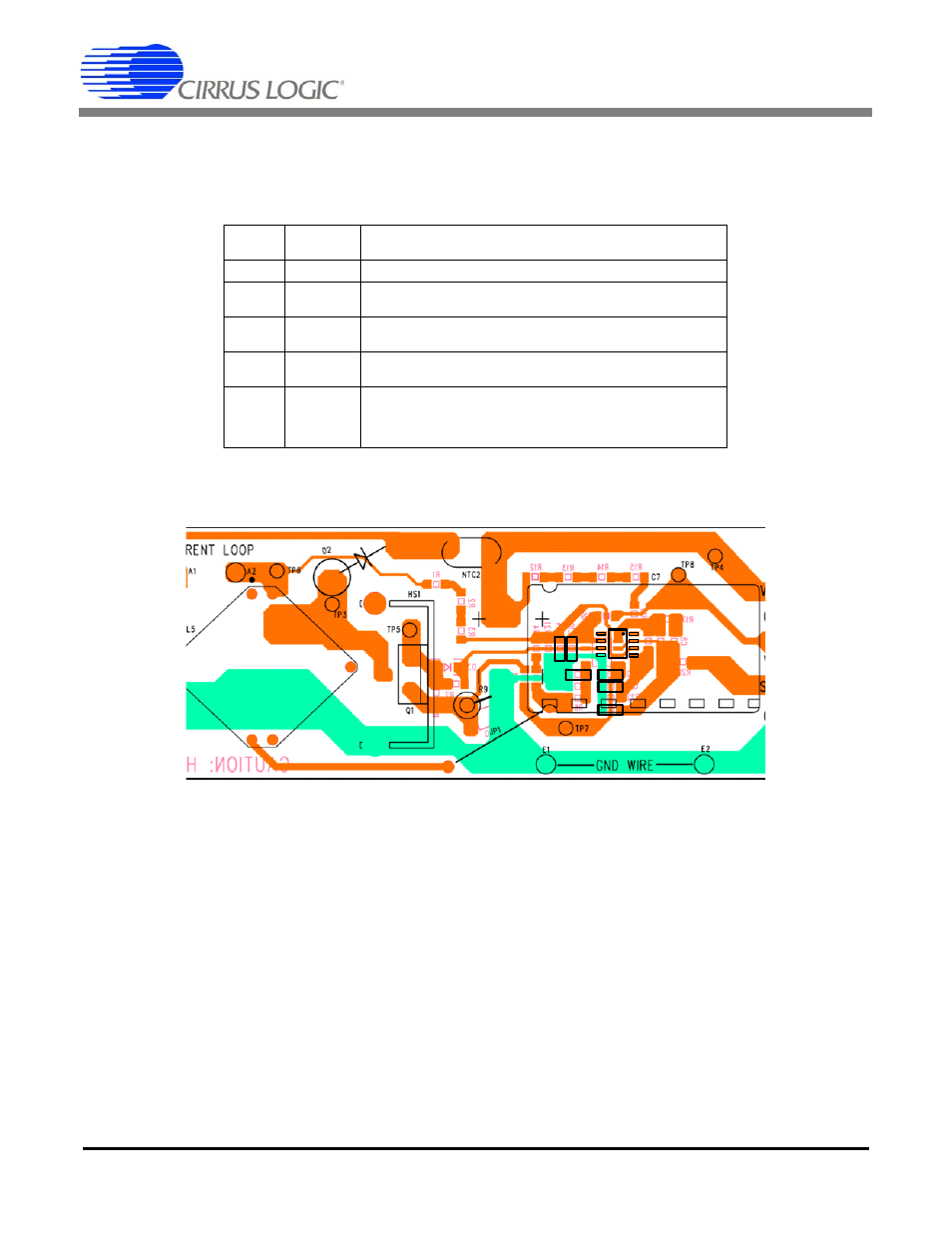
Decoupling of Sensitive Pins for CS1500
IAC (pin 3) and FB (pin 4) are noise-sensitive pins. Again, care must be taken to route these signals away
from noise sources. The following table shows the recommended decoupling for each pin.
Table 2. Recommended Decoupling for CS1500
Figure 6. Decoupling Layout for CS1500 Sensitive Signals
Pin
Number Designator
Recommended
Decoupling
1
NC
Leave as no connect.
2 STBY
Pull high through a resistor as shown in schematic. A 1nF decoupling
capacitor to ground is recommended if the pin is not used.
3 IAC
Routing should be as clean as possible. Decoupling capacitance
should be minimal. 100pF to 1nF is acceptable.
4 FB
1nF high-frequency ceramic capacitor recommended between pin 1
and GND or VDD.
7 VDD
4.7uF high-frequency ceramic capacitor between pin 8 and GND. It is
highly recommended to place this component directly between the
pins of CS1501. If the VDD is generated from the 2
nd
stage DC-DC, a
10-100 ohm resistor in series with VDD will further reduce noise.
C13
C14
C10
C15
C11
C12