1 decoupling of sensitive pins for cs1501, An346 – Cirrus Logic CS160x User Manual
Page 5
AN346
5
3.1
Decoupling of Sensitive Pins for CS1501
PFC Controllers have certain pins that are considered noise sensitive. For the CS1501 these are:
– Pin 1
IFB
– Pin 3
IAC
– Pin 4
CS (Current Sense)
– Pin 5
ZCD (Zero Current Detect)
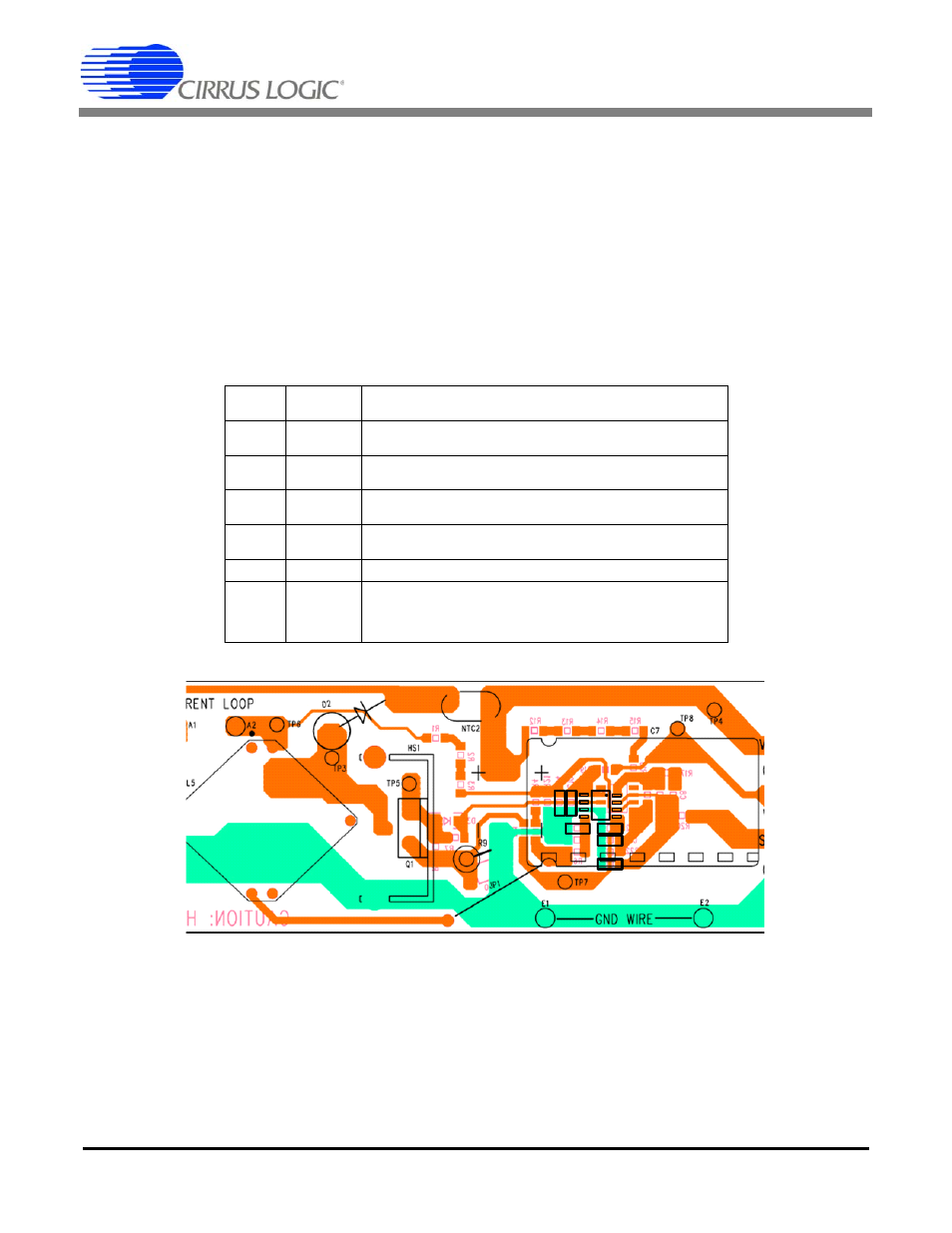
Care must be taken to route these signals away from noise sources. The following table shows the
recommended decoupling capacitors for each pin. Figure 5 shows good decoupling practices. These
traces must be as narrow as possible because the currents carried by them are on the order of 1 A. Wide
traces are prone to the capacitive coupling of noisy signals.
Table 1. Recommended Decoupling for CS1501
Figure 5. Decoupling Layout for CS1501 Sensitive Signals
Pin
Number Designator
Recommended
Decoupling
1 IFB
1nF high-frequency ceramic capacitor recommended between pin 1
and GND or VDD.
2 STBY
Pull high through a resistor as shown in schematic. A 1nF decoupling
capacitor to ground is recommended if the pin is not used.
3 IAC
1nF high-frequency ceramic capacitor recommended between pin 3
and GND or VDD.
4 CS
100pF to 1nF high-frequency capacitor recommended between pin 4
pin and GND, depending on noise injection.
5
ZCD
33pF high-frequency ceramic capacitor between pin 5 and GND.
8 VDD
4.7uF high-frequency ceramic capacitor between pin 8 and GND. It is
highly recommended to place this capacitor directly between the pins
of CS1501. If VDD is generated from the 2
nd
stage DC-DC, a 10 to
100 ohm resistor in series with VDD will further reduce noise.
C13
C14
C10
C15
C11
C12