Page 3/4 – WIKA T32.xS User Manual
Page 19
GB
19
WIKA safety manual temperature transmitter T32.xS
11583631.03 08/2014 GB/D/F/E
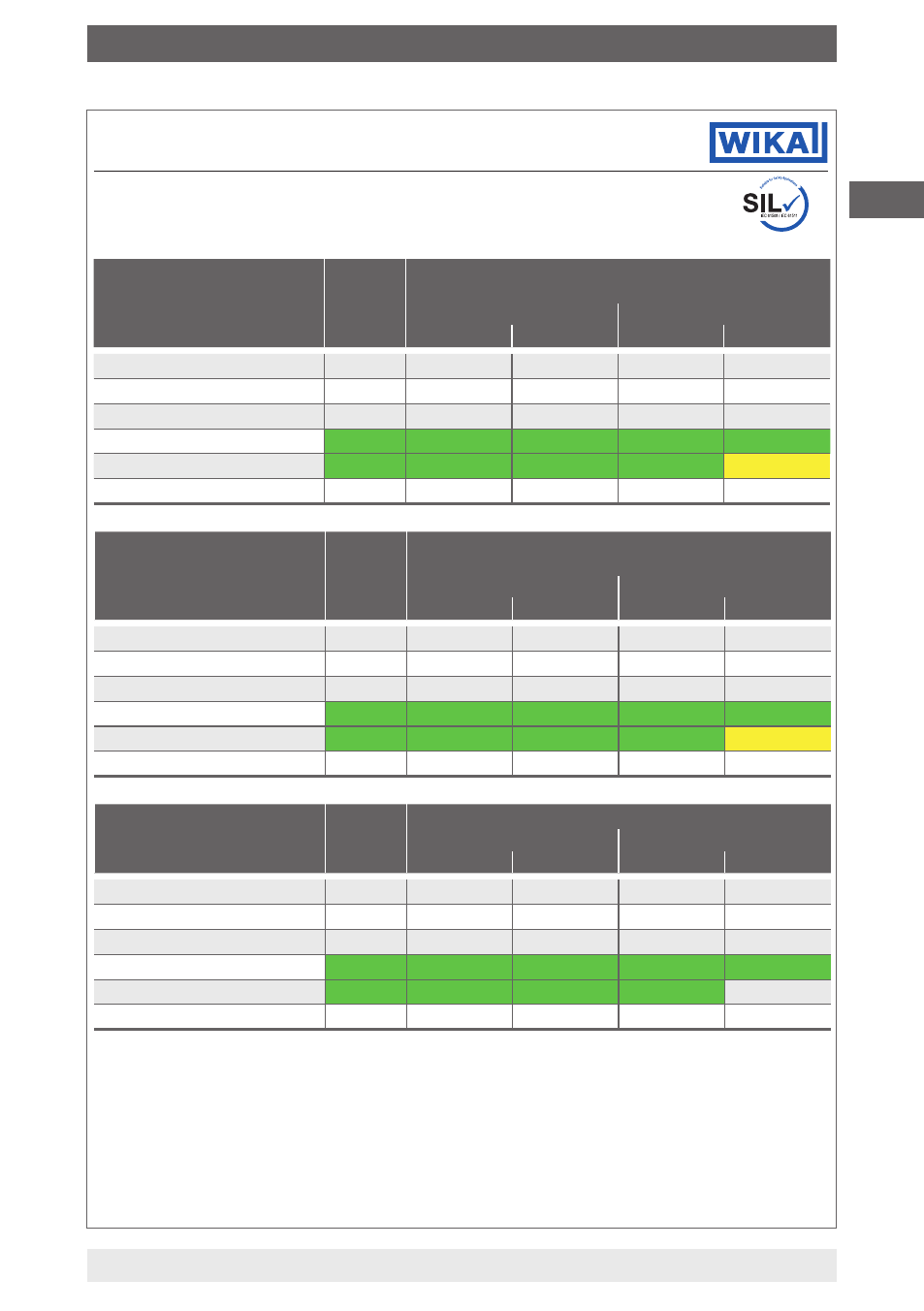
3.4 FMEDA thermocouple
with internal cold junction
(safety function for
4 … 20 mA output)
T32.xS
stand
alone
T32.xS with thermocouple (internal cold junction)
Close coupled
1)
Extension wire
2)
Low stress
3)
High stress
4)
Low stress
3)
High stress
4)
λ
DU
[FIT]
5)
10
15
210
110
2.010
λ
DD
[FIT]
5)
73
168
1.873
1.973
18.073
λ
SU
+λ
SD
[FIT]
5)
76
76
76
76
76
SFF Sensor/Transmitter
6)
- / 93,7 % 95,0 / 93,7 % 90,0 / 93,7 % 95,0 / 93,7 % 90,0 / 93,7 %
PFD
avg
for T
proof
1 year
7)
4,38 * 10
-5
6,57 * 10
-5
9,20 * 10
-4
4,82 * 10
-4
8,80 * 10
-3
DC diagnostic coverage
99,0 %
-
-
-
-
3.5 FMEDA thermocouple
with external cold
junction (safety function for
4 … 20 mA output)
T32.xS
stand
alone
T32.xS with thermocouple (external cold junction
8)
)
Close coupled
1)
Extension wire
2)
Low stress
3)
High stress
4)
Low stress
3)
High stress
4)
λ
DU
[FIT]
5)
11
24
228
119
2.019
λ
DD
[FIT]
5)
76
210
1.954
2.015
18.115
λ
SU
+λ
SD
[FIT]
5)
76
76
76
76
76
SFF Sensor/Transmitter
6)
- / 93,4 % 90,8 / 93,4 % 89,6 / 93,4 % 94,7 / 93,4 % 90,0 / 93,4 %
PFD
avg
for T
proof
1 year
7)
4,70 * 10
-5
1,07 * 10
-4
9,99 * 10
-4
5,23 * 10
-4
8,84 * 10
-3
DC diagnostic coverage
99,0 %
-
-
-
-
3.6 FMEDA duplex sensor
Pt100 (safety function for
4 … 20 mA output)
T32.xS
stand
alone
T32.xS with duplex sensor Pt100
Close coupled
1)
Extension wire
2)
Low stress
3)
High stress
4)
Low stress
3)
High stress
4)
λ
DU
[FIT]
5)
10
27
390
356
3.810
λ
DD
[FIT]
5)
75
154
1.599
1.649
15.275
λ
SU
+λ
SD
[FIT]
5)
76
76
76
76
76
SFF Sensor/Transmitter
6)
- / 93,8 % 82,0 / 93,8 % 80,0 / 93,8 % 82,0 / 93,8 % 80,0 / 93,8 %
PFD
avg
for T
proof
1 year
7)
4,36 * 10
-5
1,19 * 10
-4
1,71 * 10
-3
1,56 * 10
-3
1,67 * 10
-2
DC diagnostic coverage
99,0 %
-
-
-
-
Appendix: SIL declaration of conformity
SIL Declaration of Conformity
Functional safety per IEC 61508:2010 / IEC 61511:2004
Page 3/4
1) Close coupled: The temperature transmitter is located in the connection head of the electrical thermometer.
2) Extension wire: The temperature transmitter is located outside of the connection head of the electrical thermometer, for
example in a cabinet distant from the measuring point
3) Low stress applies to a low vibration environment or the use of a cushioned sensor. Operation below 67 % maximum rating
according to specification
4) High stress applies to a high vibration environment. Operation above 67 % maximum rating according to specification
5) FIT = Failure in time, Unit: Quantity of failures per 10
9
h
6) Green marked values: SFF sufficient for SIL 2
7) Green marked values: PFD
avg
< 35 % of the maximum allowed value for SIL 2 (PFD
avg
< 0,0035)
Yellow marked values: PFD
avg
< maximum allowed value for SIL 2 (PFD
avg
< 0,01)
8) Assumption: low stress, close coupled for external Pt100 sensor