Version with lcd-display (optional) – WIKA 891.34.2189 User Manual
Page 8
GB
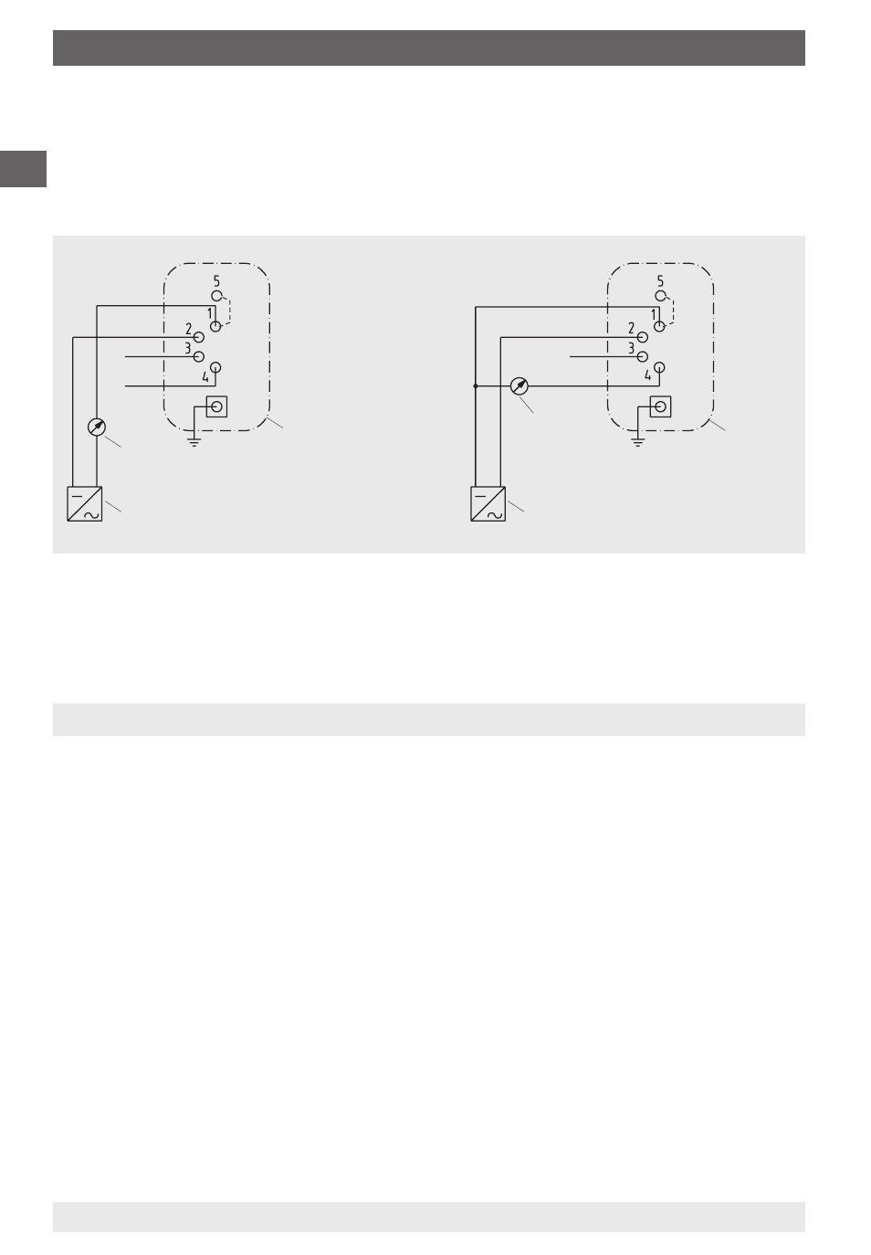
6. Wiring details / 7. Version with LCD-display (optional extra)
Test +
0 V / S-
UB+ / S+
Test -
1416 324.03
Evaluation
(display/recorder)
mA
Power supply
Power suppy
Evaluation
(display/re-
corder)
Connector
housing
Connector
housing
0 V / S-
S+ / Test-
UB+
Test +
mA
2279453 08/2009 GB/D/F
WIKA Operating Instructions Differential Pressure Transmitter DELTA-trans
8
Terminal assignment
Terminals 1 and 5 are bridged internally within the connector, so that two termi-
nals are available for the 0 V / S - connection.
4 ... 20 mA 2-wire system
0 ... 20 mA 3-wire system
The transmitter can operate using a non-stabilised supply voltage within the
given limits, so long as the voltage available to the transmitter does not fall
below 10 V, or below 14 V for the LCD-display version.
7. Version with LCD-display (optional)
On integrated LCD-displays, for local pressure read-out, the output signal is 2-
wire 4 ... 20 mA. For the required power supply for the integrated LCD display,
please refer to Chapter 8, Technical Data.
Limitation on zero point and span adjustment:
If an LCD display is integrated, it must be noted that the zero point and span
adjustment is only to be used for resetting the measuring range. Changes to
the measuring range, made using the zero and span adjustment will not be
shown on the display.