WIKA WU-26 User Manual
Page 81
81
WIKA Operating instructions/Betriebsanleitung/Mode d'emploi/Instrucciones de servicio, WU-2X
11553678.02 GB/D/F/E 10/2012
GB
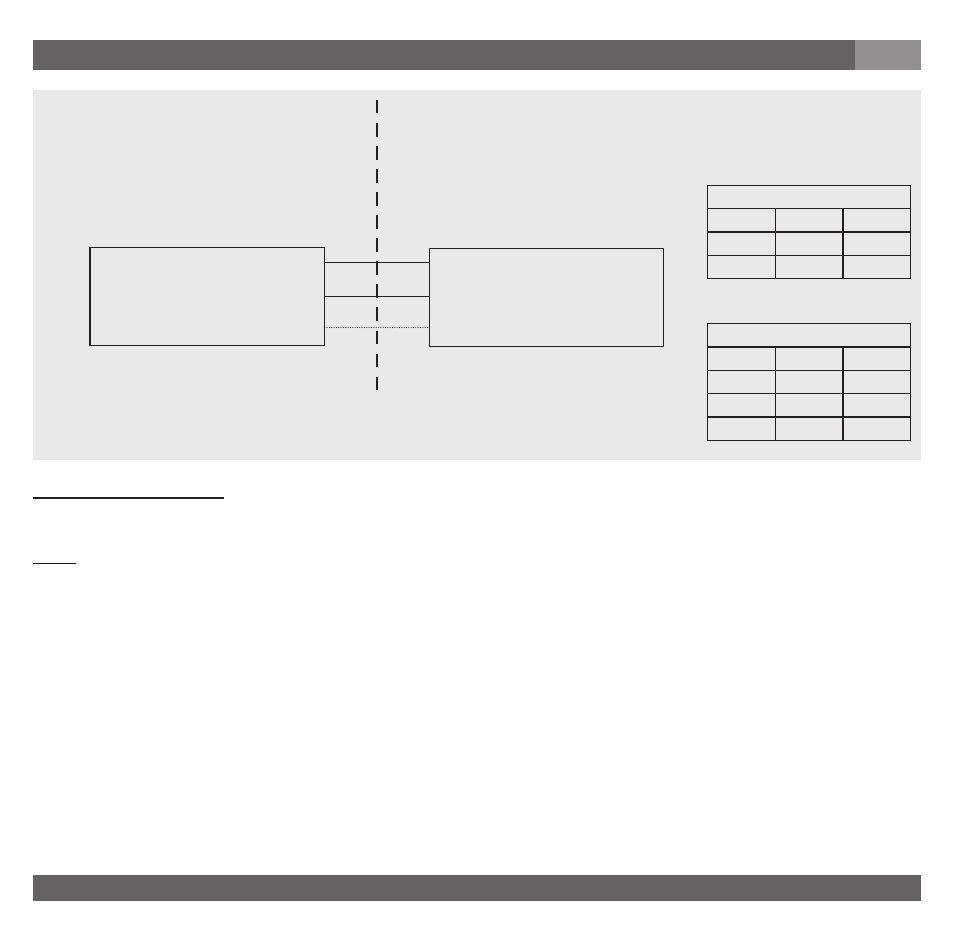
Control Drawing No. 11537885
Hazardous (Classified) Location
Non-Incendive Installation
Class I, Division 2, Groups A, B, C and D
Class I, Zone 2, Group IIC
(Note 3)
Non-Hazardous Location
Series WU-2*
U+ / S+
Non-incendive
Transmitter
U- / S-
S+
Control Equipment
(Note 4), (Note 5)
2 wire system
wire
coding
color
supply +
U+ / S+
red
supply -
U- /S-
black
3 wire system
wire
coding
color
supply +
U+
red
supply -
U- /S-
black
signal +
S+
brown
Non-incendive Parameters
V
max
= 10 ... 31 V DC, I
max
= 30 mA (Note 2), Ci = 11 nF (+ 0,3 nF/m with cable), Li = 10 µH (+ 2 µH/m with cable)
Notes
1. The non-incendive field wiring concept allows the interconnection of two devices with non-incendive parameters not
specifically examined in combination as a system when:
Uo or Voc ≤ Vmax, Ca or Co ≥ Ci + Ccable, La or Lo ≥ Li + Lcable, Po ≤ Pi
2. For this current controlled circuit, the parameter I
max
is not required to be aligned with the parameter I
sc
or I
t
of non-incen-
dive field wiring apparatus.
3. Installation shall be in accordance with the National Electrical Code
(ANSI/NFPA70) Sections 504 and 505.
4. The configuration of Control Equipment must be under non-incendive field wiring concept and FM Approved.
5. Control Equipment manufacturer`s installation drawing must be followed when installing this equipment.
6. No revision to this drawing without prior approval by FM.