Connecting the assembly cable – Sunlight Supply Samsung Linesets for Mini Split Systems User Manual
Page 30
30
Connecting the assembly cable
• End of the wire must be circular.
• After connecting the cables, make sure terminal numbers on the indoor/outdoor unit matches.
• Screws on terminal block must not be unscrewed with the torque less than 0.87ft
•
lb(12kgf
•
cm).
10. Connect the grounding conductor to the grounding terminals.
11. Close the terminal board cover by tightening the screw carefully.
• In Russia and Europe, consult with the supply authority to determine the supply system impedance before
installation.
• Connect the wires firmly so that wires can not be pulled out easily.
(If they are loose, it could cause burn-out of the wires.)
• Connect the wires according to color codes, referring to the wiring diagram.
• The power cable and the interconnection cable should be selected according to the specification in page 28.
Installing and connecting the assembly pipe of the indoor unit
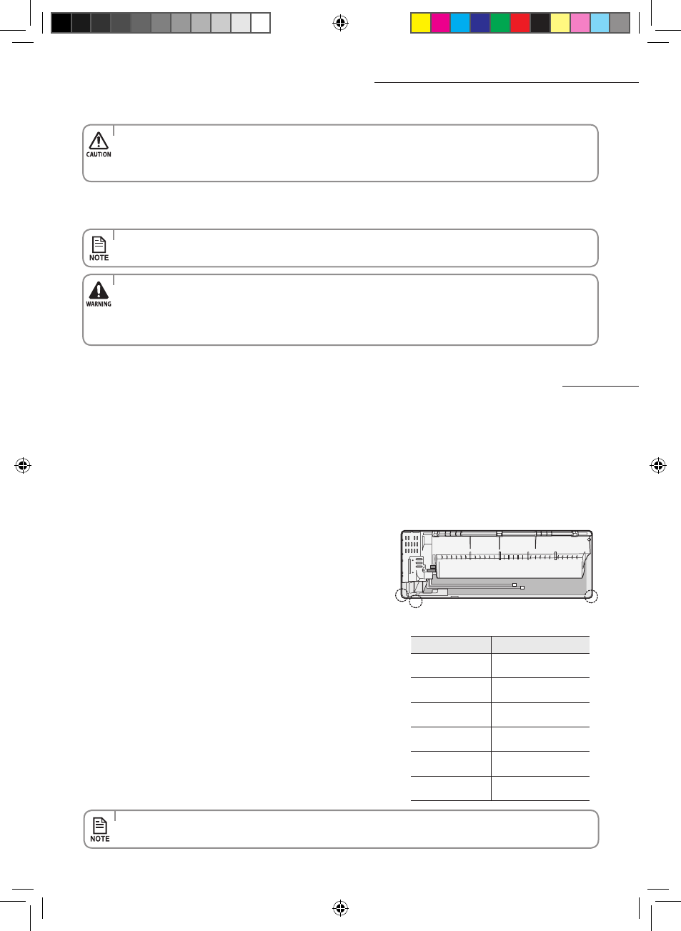
1. Cut out the appropriate knock-out piece (A, B, C) on the rear of the
indoor unit unless you connect the pipe directly from the rear.
2. Smooth the cut edges.
3. Remove the protection caps of the pipes and connect the assembly
pipe to each pipe. Tighten the nuts first with your hands, and then
with a torque wrench, applying the following torque:
Connect indoor and outdoor units with field-supplied copper pipes by means of flare connections. Use insulated seamless
refrigeration grade pipe only, (Cu DHP type according to ISO1337), degreased and deoxidized, suitable for operating pressures
of at least 4200 kPa and for burst pressure of at least 20700 kPa. Under no circumstances must sanitary type copper pipe be
used.
There are 2 refrigerant pipes of different diameters:
• The smaller one is for the liquid refrigerant
• The larger one is for the gas refrigerant
A short pipe is already fitted to the air conditioner. You may
need to extend the pipe using the assembly pipe (optional).
The connection procedure for the refrigerant pipe varies
according to the exit position of the pipe when facing the wall:
• Right(A)
• Left(B)
• Underside(C)
• Rear
B
A
C
Outer Diameter
Torque
ø1/4 inch
(ø6.35mm)
10.1~12.3 ft.lb
(140~170 kgf.cm)
ø3/8 inch
(ø9.52mm)
18.1~20.3 ft.lb
(250~280 kgf.cm)
ø1/2 inch
(ø12.70 mm)
27.5~30.4 ft.lb
(380~420 kgf.cm)
ø5/8 inch
(ø15.88mm)
31.8~34.7 ft.lb
(440~480 kgf.cm)
ø3/4 inch
(ø19.05mm)
71.6~87.5 ft.lb
(990~1210 kgf.cm)
ø7/8 inch
(ø22.23 mm)
71.6~87.5 ft.lb
(990~1210 kgf.cm)
• If you want to shorten or extend the pipes, refer to page 31~32.
Vivaldi MAX_AQN09VFU@@ IB&IM_32163A_E.indd 30
2012-6-20 13:28:59