M&G DuraVent DuraStack® User Manual
Page 31
31
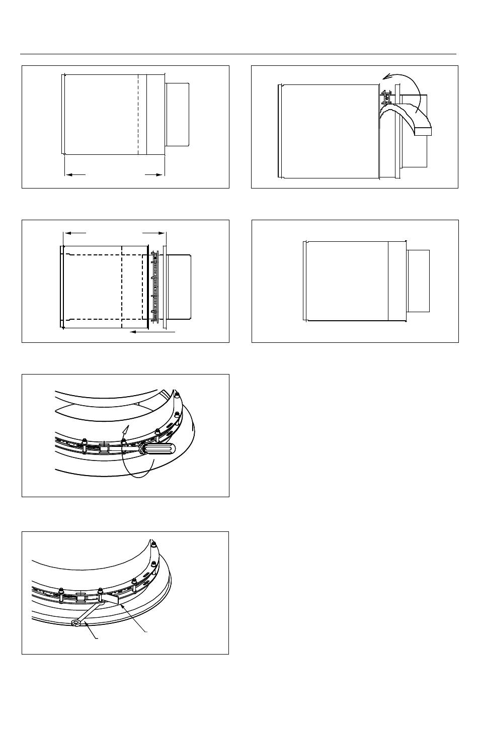
Figure 51
Figure 52
Figure 53
Figure 54
Figure 55
Figure 56
VarIaBLE LEngtH
1. The variable length (LV) is used only to
make odd lengths, it doesn’t compensate
thermal expansion. See Figure 65 for typical
location.
2. The variable length assembly includes a
sliding flanged female coupling, a flanged
retaining band, a locking band, a insulation
band and split outer casing. Inner flue sealant
S-2000 or S-650 is necessary depending on
the flue gaz temperature.
3. Installation steps :
a. Measure the distance required for the
variable length. See Figure 58.
b. Cut the inner wall at the dimension
found at point ‘a.’ plus 1”. Cut the split outer
casing at dimension plus 5/8”. Then cut the
insulation band at dimension (DIS only). See
Figure 59.
c. Install the interior assembly between the
two parts. Put one bead of sealant between
the couplings flanges as a regular length
installation. See Figure 60.
Desired Length
Desired Length
Move Outer Casing
Supplied Tool
Wrench