M&G DuraVent DuraStack® User Manual
Page 12
12
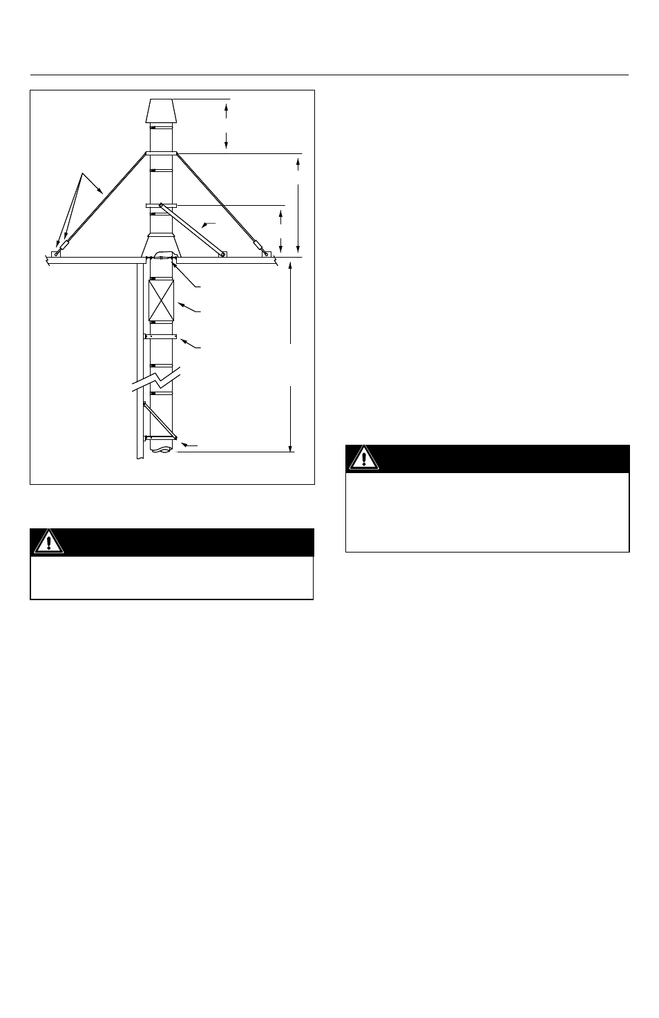
4. When using guy wire, the cable must
be slightly slack or loose to allow thermal
expansion.
5. When using rigid bracing, the maximum
vertical height between supports must
be reduced to 5’ to compensate thermal
expansion.
tErmInatIon HEIgHt
Chimneys and vents shall terminate above
the roof level in accordance with the
following requirements:
1. Five feet above the roof level or any
adjacent flat roof, wall parapet or air intakes,
and/or in accordance with the following
NFPA 211 requirements.
2. Where chimney terminates at less than 10
Figure 8
feet from any adjacent ridge, wall or parapet,
the chimney shall terminate at minimum of 3
feet above the ridge, wall, or parapet.
3. Where chimney terminates at more than 10
feet from ridge, wall, or parapet, a minimum
height of 2 feet shall be required above the
ridge wall or parapet.
muLtI-EngInE EXHauSt SyStEmS
A common exhaust system for multiple
engine or turbine installations is generally
not recommended. A separate exhaust
system should be provided for each engine
or turbine. Check with your engine or turbine
manufacturer prior to common exhaust
system design. Exhaust gas from operating
units tends to flow to non-operating units
where condensation may form.
Important
Water in engine or turbines at start-up
may cause damage. In general, a separate
exhaust system should be provided for
each engine or turbine.
SECtIon B- tEES, ELBoWS, InCrEaSErS
90° tEE (t90)
1. Generally used to connect the horizontal
length from the appliance to the vertical
length when clean-outs access or drain is
required.
2. 90° should not be used for changing flow
direction in diesel or turbine exhaust.
3. For supporting the tee, the preferred
location is above the tee (see Figure 9).
4. If it is not possible to suspend the tee, it
may be supported from the base (see Figure
10). When this is necessary, a short length
should be installed between the tee and the
tee cap or Drain-Tee Cap for a good clean-out
or inspection access.
Important
Cables and roof anchors designed for 30 lb.
per sq. ft. force on chimney projected area.
See Table 7 for "H" dimensions
Maximum
Height
- See
Table 6
H
H
Guy Cable * tensioners
and roof anchors * (by
others)
Support
Expansion
Length
Guide
Support
Brace
5' Max