M&G DuraVent DuraStack® User Manual
Page 10
10
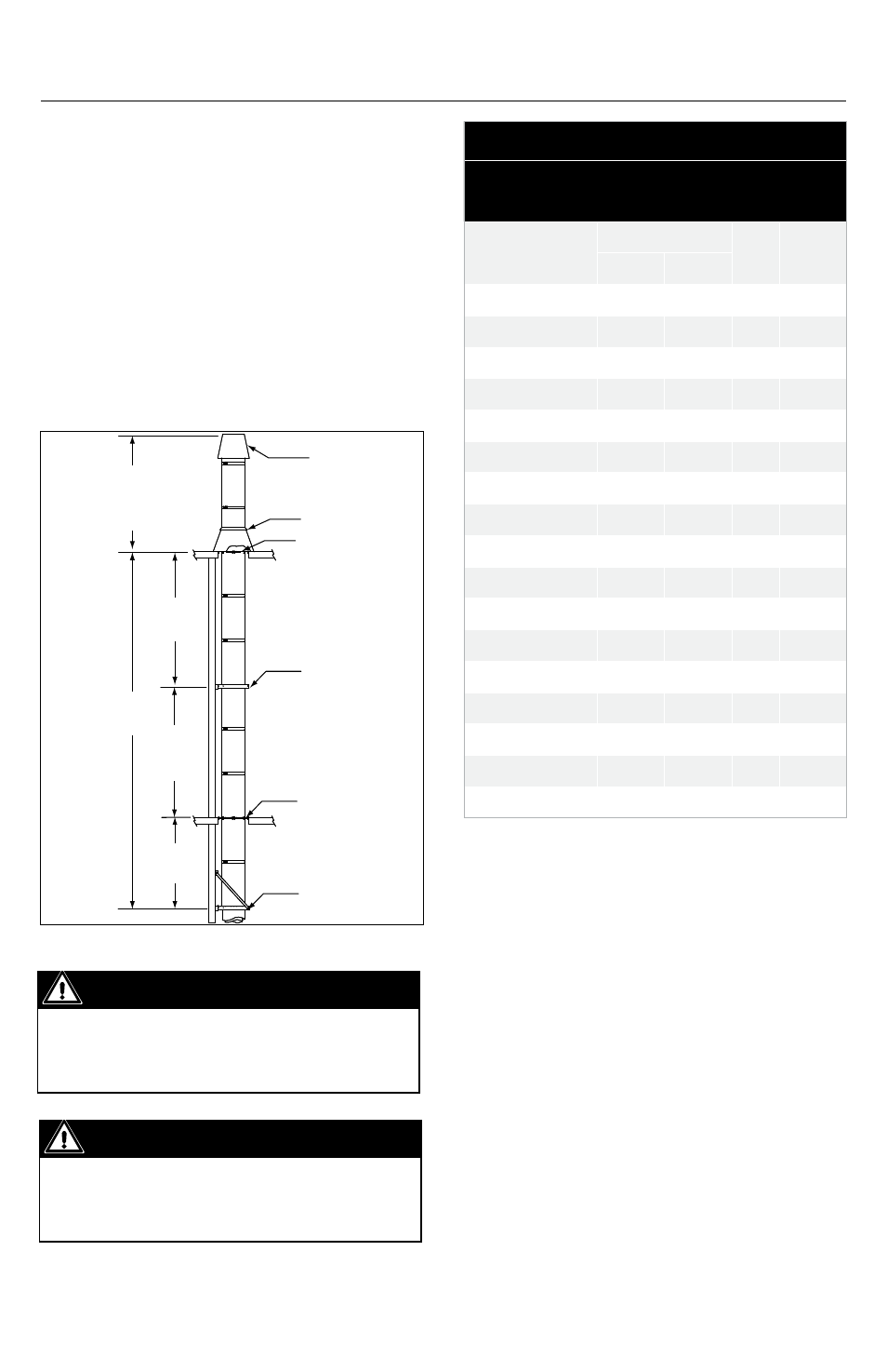
Figure 6
Important
When the maximum height from
Table 6 is exceeded, resupport using
another support and expansion joint.
Support mEtHoDS anD HEIgHt LImItS
1. Several support and guiding methods are
used to anchor a chimney against upward,
downward and angular displacement.
2. These supports and guides used with
thermal expansion devices, prevent bending
stresses on the chimney elbows and joints.
3. Supports and guiding methods and
installation are described in Section
C. Certain limitations apply for proper
installation of supports and guides. See
Tables 6 and 7.
Table 7
Support and Guide Spacing for Model
DIS and DAS (dimensions in feet)
Inside Diameter
(in.)
MVS*
H** MHS***
Interior Exterior
5
10
8
10
12
6
10
8
10
12
8
10
8
10
12
10
10
8
10
12
12
10
8
10
12
14
10
8
10
12
16
10
8
10
12
18
10
8
10
12
20
10
8
10
12
22
10
8
10
12
24
10
8
10
12
26
10
8
10
12
28
10
8
10
12
30
10
8
10
12
32
10
8
10
12
34
10
8
10
12
36
10
8
10
12
* MVS: Maximum Vertical Spacing between two guides or a
support and a guide in a vertical position.
** H: Maximum freestanding Height above the roof.
*** MHS: Maximum Horizontal Spacing between two guides or a
support and a guide is 12 feet.
tHErmaL EXpanSIon
Good installation practice requires that
any length of exhaust system between two
fixed points subject to more than 1/4 inch
expansion must have an Adjustable Length
(LA) or Bellows Joint (LB) to compensate
for expansion. Models DIS and DAS will
expand approximately 1 inch for every 100°F
temperature rise per 100 feet of chimney.
To accommodate chimney movements, any
wall guide or floor guide must be located
Important
“MVS ” dimension see Table 7 for
Maximum Vertical Spacing between two
guides or a support and a guide.
Termination
Storm Collar
Roof Support
Wall Guide
See Dim. "H" Figure 7
and Chimney Guying and
Bracing in this section
Maximum
Height - See
Table 6
MVS
MVS
MVS
Floor Guide
Wall Support